
Key Takeaways:
- High precision optical tolerances are crucial for optical components, affecting dimension, thickness, curvature, angular alignment, bevel, surface quality, irregularity, and finish.
- Optical tolerances control precision and costs, ranging from base to high precision in manufacturing.
Optical Tolerances
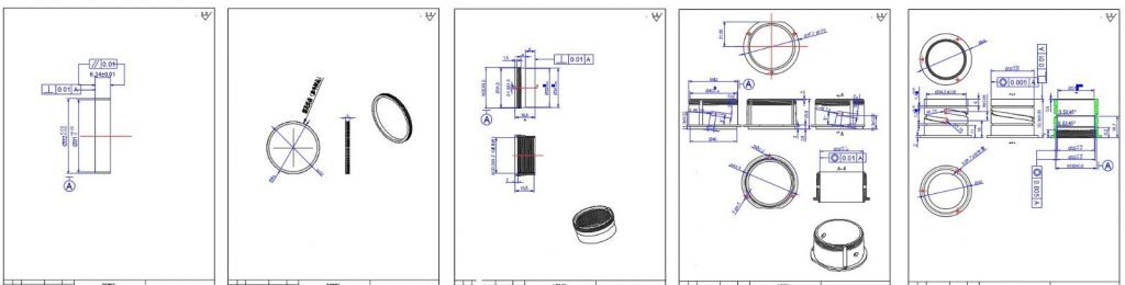
In real manufacturing, a certain amount of error will unpreventably occur between the measured value and the designed value. In terms of measurement, the difference between the maximum and minimum dimensions of permissible errors is called tolerance. If it is written on the drawing that “3.5 +0.05/-0.00“, “3.5” represents the reference dimension, “+0.05” represents the tolerance of the upper limit, “-0.00” represents the lower limit. The precision of optical tolerances greatly impacts the performance and cost of an optical component or system. Optical components usually have more stringent requirements for tolerances compared to mechanical components. The cost of an optical component can be influenced by various factors such as quantity, material, surface shape, size, dimension and diameter tolerances, surface figure accuracy, surface quality, coating requirements, and delivery time.
Cost Drivers for Optical Components:
Quantity
- Material
- Surface Shape
- Size
- Dimension/Diameter Tolerances
- Surface Figure Accuracy
- Surface Quality (Scratch & Dig)
- Coating Requirements
- Delivery Time
Optical tolerance classes:
- Base: typical, no added cost for exceeding optical tolerances beyond this level
- Precision: requires extra attention, easily achievable in most shops, may cost 25% more
- High Precision: necessitates special equipment or personnel, may cost 100% more (double)
The followings are the definitions of typical optical parameters and their corresponding optical tolerances:
Dimension/Diameter Tolerance defines the acceptable range for the diameter of a lens, mirror, or any other optical component. Although diameter tolerance has no effect on optical performance, it is a crucial mechanical tolerance that must be considered if the component is going to be assembled with other parts. The table below shows typical manufacturing tolerances.
Base
Precision
High Precision
100 μm
25 μm
6 μm
Center Thickness Tolerance represents the permitted error in the thickness of a lens or filter, measured at its center across the mechanical axis of the lens. As the center thickness affects the optical path length of rays passing through a lens, it can impact optical performance. The following table displays typical manufacturing tolerances.
Base
Precision
High Precision
200 μm
50 μm
10 μm
Radius of Curvature refers to the distance between the vertex of an optical component and its center of curvature. It can be positive, zero, or negative based on the shape of the lens. Knowing this value helps to determine the optical path length of rays passing through the lens or mirror and plays a role in determining its power. The table below illustrates typical manufacturing tolerances.
Base
Precision
High Precision
0.2%
0.1%
0.01%
Angular Tolerance in components like prisms and beamsplitters represents the maximum deviation allowed between the angles of adjacent sides of an optical prism. It is usually been measured by autocollimator assembly, whose light source system emits collimated light. The table below demonstrates typical manufacturing tolerances.
Base
Precision
High Precision
6 arc min
1 arc min
15 arc sec
A Bevel is used to protect delicate glass corners from chipping. Chipped edges can cause problems during the lapping/polishing processes and result in scratches. Beveled edges also protect those handling the components, as handling machined glass without bevels can lead to cuts. Bevel is defined by the face width and angle. It is most commonly cut at 45°, and face width is determined by the diameter of the optic. The following table displays typical manufacturing tolerances.
Base
Precision
High Precision
0.2 mm
0.1 mm
0.02 mm
Surface Quality of an optical component refers to any defects such as scratches or pits, also known as digs. In many cases, these defects are purely cosmetic and do not significantly affect optical performance. The most common way to specify surface quality is through scratch/dig. The scratch designation is determined by comparing the test surface to a set of standard scratches under controlled lighting conditions, so it does not describe the scratch itself but instead compares it to a standardized scratch. The dig designation directly describes the dig and is calculated as the diameter of the dig in microns divided by 10. The following table shows typical specifications.
Base
Precision
High Precision
80/50
60/40
20/10
Surface Irregularity describes how the shape of a surface deviates from the shape of s reference shape. The comparison leads to the formation of circular fringes, which reveal the consistency or inconsistency of the surface. Unlike surface quality, Surface Irregularity plays a crucial role in determining the effectiveness of an optical system. The accepted manufacturing standards for Surface Irregularity can be found in the accompanying table.
Base
Precision
High Precision
1 wave
λ/4
λ/20
Additionally, Surface Finish or Surface Roughness assesses the minute deviations on the surface of an optical component. The prescribed manufacturing standards for these characteristics are also listed in the table.
Base
Precision
High Precision
50 Å rms
20 Å rms
20 Å rms


GREAT ARTICLE!
Share this article to gain insights from your connections!
