
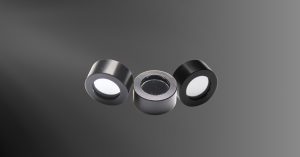
Bandpass Filters
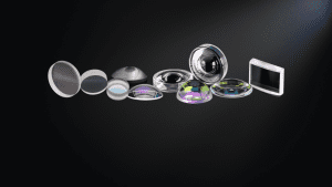
Bandpass filters are optical filters designed to transmit a defined spectral band while blocking or attenuating wavelengths outside that range. Depending on the application, the passband may be narrower than 1 nm for laser, fluorescence, or spectroscopy systems, or broad enough to span tens to hundreds of nanometers for imaging, sensing, and illumination. Bandpass filters typically use thin-film interference coatings on substrates such as optical glass, fused silica, sapphire, or infrared-transmitting materials, with the coating and substrate selected to support UV, visible, NIR, SWIR, MWIR, or LWIR performance requirements.
Avantier offers both stock bandpass filters and custom optical filter solutions tailored to specific wavelength, bandwidth, transmission, blocking, substrate, size, and environmental needs.
Applications
Bandpass filters are essential in optical systems that require selective spectral transmission, enabling a defined wavelength range to pass while suppressing unwanted out-of-band radiation. Common applications include clinical chemistry instrumentation, immunoassays, fluorescence, color separation, flame photometry, elemental and laser line separation, spectral radiometry and environmental testing.
Key performance requirements are typically defined by the spectral region of interest, required transmission, blocking level, optical density, angle of incidence, thermal stability, and integration constraints within the optical system.


Understanding bandpass filters
A bandpass filter may be as simple as a combination of a high-pass filter and a low-pass filter. Most optical bandpass filters use multilayer thin-film interference coatings, where alternating layers of materials with different refractive indices cause certain wavelengths to constructively interfere and pass through the filter. Wavelengths outside the target passband undergo destructive interference, reflection, absorption, or attenuation, depending on the filter design, resulting in spectral performance that is defined by parameters such as center wavelength, bandwidth, peak transmission, and out-of-band blocking.
Specifications
| Parameter | Standard & Custom Capability |
| Substrates | Standard: B270, UV Fused Silica, BK7Custom: Sapphire, Silicon, Germanium, ZnSe, ZnS (for MWIR/LWIR), or customer-supplied material |
| Coating Type | Hard-coated multilayer dielectric interference coatings (Ion-Assisted Deposition / IBS); Soft-coated options available for prototyping |
| Peak Transmission (%T) | Standard: > 90% (VIS-NIR) High Precision: > 95% available; UV/MWIR/LWIR typically > 85% depending on bandwidth |
| Center Wavelength (CWL) | Stock: 214 nm to 10.6 µm (see stock tables below)Custom: 193 nm to 14 µm; Tolerances down to ±0.1 nm (laser-line) |
| Full-Width Half-Maximum (FWHM) | Stock: From < 1 nm (ultra-narrow) to > 100 nm (broadband) Custom: Fully tunable per specification; tolerance ±0.5 nm to ±5 nm |
| Pass Band Ripple | Standard: < ±0.3 dB (or < 5% peak-to-peak) for flat-top designs; Gaussian profiles available upon request |
| Edge Steepness | Defined by the transition from 50% T to < 1% T. Typical steepness is < 1% of CWL for high-end designs |
| Blocking Range | Standard Blocking: Deep-UV to 1200 nm (VIS/NIR) or spectral limits of substrateOptical Density (OD): OD ≥ 4.0 (standard), OD ≥ 6.0 available for laser applications |
| Surface Quality | Standard: 40-20 (MIL-PRF-13830B)High Precision: 10-5 (available for low-scatter |
Stock Bandpass Filters
| Part Number | Size (mm) | Central Wavelength (nm) | FWHM (nm) | Peak Transmittance | Block Wavelength (nm) | OD | Price (USD) | Delivery Time |
|---|---|---|---|---|---|---|---|---|
| AVTJS-0100 | φ12.7 | 315 | 20±3 | >70% | 200-850 | >OD5 | $200.00 | One Week |
| AVTJS-0101 | φ12.7 | 360 | 90±10 | >90% | 200-920 | >OD5 | $200.00 | One Week |
| AVTJS-0102 | φ12.7 | 365 | 20±3 | >90% | 200-730 | >OD5 | $200.00 | One Week |
| AVTJS-0103 | φ12.7 | 380 | 60±10 | >90% | 200-1000 | >OD5 | $200.00 | One Week |
| AVTJS-0104 | φ12.7 | 395 | 20±3 | >90% | 200-1100 | >OD4 | $200.00 | One Week |
| AVTJS-0105 | φ12.7 | 400 | 20±3 | >90% | 200-1100 | >OD5 | $200.00 | One Week |
| AVTJS-0106 | φ12.7 | 400 | 45±5 | >95% | 200-1100 | >OD5 | $200.00 | One Week |
| AVTJS-0107 | φ12.7 | 405 | 30±5 | >90% | 200-1200 | >OD7 | $200.00 | One Week |
| AVTJS-0108 | φ12.7 | 405 | 40±5 | >90% | 200-1100 | >OD5 | $200.00 | One Week |
| AVTJS-0109 | φ12.7 | 420 | 20±3 | >90% | 200-1100 | >OD5 | $200.00 | One Week |
| AVTJS-0110 | φ12.7 | 425 | 50±5 | >95% | 200-1100 | >OD5 | $200.00 | One Week |
| AVTJS-0111 | φ12.7 | 435 | 20±3 | >95% | 200-1100 | >OD5 | $200.00 | One Week |
| AVTJS-0112 | φ12.7 | 450 | 20±3 | >95% | 200-1100 | >OD5 | $200.00 | One Week |
| AVTJS-0113 | φ12.7 | 450 | 50±5 | >95% | 200-1100 | >OD5 | $200.00 | One Week |
| AVTJS-0114 | φ12.7 | 450 | 100±10 | >95% | 200-1100 | >OD5 | $200.00 | One Week |
| AVTJS-0115 | φ12.7 | 455 | 25±4 | >95% | 200-1100 | >OD5 | $200.00 | One Week |
| AVTJS-0116 | φ12.7 | 460 | 20±3 | >95% | 200-1100 | >OD5 | $200.00 | One Week |
| AVTJS-0117 | φ12.7 | 460 | 35±5 | >95% | 200-1100 | >OD5 | $200.00 | One Week |
| AVTJS-0118 | φ12.7 | 470 | 40±5 | >95% | 200-1100 | >OD5 | $200.00 | One Week |
| AVTJS-0119 | φ12.7 | 470 | 85±10 | >95% | 200-1100 | >OD5 | $200.00 | One Week |
| AVTJS-0120 | φ12.7 | 475 | 25±4 | >95% | 200-1100 | >OD5 | $200.00 | One Week |
| AVTJS-0121 | φ12.7 | 475 | 50±5 | >95% | 200-1100 | >OD5 | $200.00 | One Week |
| AVTJS-0122 | φ12.7 | 500 | 20±3 | >95% | 200-1100 | >OD5 | $200.00 | One Week |
| AVTJS-0123 | φ12.7 | 500 | 40±5 | >95% | 200-1100 | >OD5 | $200.00 | One Week |
| AVTJS-0124 | φ12.7 | 500 | 50±5 | >95% | 200-1100 | >OD5 | $200.00 | One Week |
| AVTJS-0125 | φ12.7 | 525 | 30±5 | >95% | 200-1100 | >OD5 | $200.00 | One Week |
| AVTJS-0126 | φ12.7 | 525 | 40±5 | >95% | 200-1100 | >OD5 | $200.00 | One Week |
| AVTJS-0127 | φ12.7 | 532 | 20±3 | >95% | 200-1100 | >OD5 | $200.00 | One Week |
| AVTJS-0128 | φ12.7 | 532 | 50±5 | >95% | 200-1100 | >OD5 | $200.00 | One Week |
| AVTJS-0129 | φ12.7 | 540 | 20±3 | >95% | 200-1100 | >OD5 | $200.00 | One Week |
| AVTJS-0130 | φ12.7 | 550 | 25±4 | >95% | 200-1100 | >OD5 | $200.00 | One Week |
| AVTJS-0131 | φ12.7 | 550 | 40±5 | >95% | 200-1100 | >OD5 | $200.00 | One Week |
| AVTJS-0132 | φ12.7 | 550 | 50±5 | >95% | 200-1100 | >OD5 | $200.00 | One Week |
| AVTJS-0133 | φ12.7 | 550 | 100±10 | >95% | 200-1100 | >OD5 | $200.00 | One Week |
| AVTJS-0134 | φ12.7 | 560 | 20±3 | >95% | 200-1100 | >OD5 | $200.00 | One Week |
| AVTJS-0135 | φ12.7 | 570 | 20±3 | >95% | 200-1100 | >OD5 | $200.00 | One Week |
| AVTJS-0136 | φ12.7 | 570 | 40±5 | >95% | 200-1100 | >OD5 | $200.00 | One Week |
| AVTJS-0137 | φ12.7 | 576 | 30±5 | >95% | 200-1200 | >OD7 | $200.00 | One Week |
| AVTJS-0138 | φ12.7 | 590 | 20±3 | >95% | 200-1100 | >OD5 | $200.00 | One Week |
| AVTJS-0139 | φ12.7 | 590 | 30±5 | >95% | 200-1100 | >OD5 | $200.00 | One Week |
| AVTJS-0140 | φ12.7 | 590 | 40±5 | >95% | 200-1100 | >OD5 | $200.00 | One Week |
| AVTJS-0141 | φ12.7 | 600 | 20±3 | >95% | 200-1100 | >OD5 | $200.00 | One Week |
| AVTJS-0142 | φ12.7 | 600 | 40±5 | >95% | 200-1100 | >OD5 | $200.00 | One Week |
| AVTJS-0143 | φ12.7 | 610 | 35±5 | >95% | 200-900 | >OD5 | $200.00 | One Week |
| AVTJS-0144 | φ12.7 | 615 | 20±3 | >95% | 200-1100 | >OD5 | $200.00 | One Week |
| AVTJS-0145 | φ12.7 | 615 | 30±5 | >95% | 200-1100 | >OD3 | $200.00 | One Week |
| AVTJS-0146 | φ12.7 | 630 | 20±3 | >95% | 200-1100 | >OD5 | $200.00 | One Week |
| AVTJS-0147 | φ12.7 | 635 | 20±3 | >95% | 200-1100 | >OD5 | $200.00 | One Week |
| AVTJS-0148 | φ12.7 | 640 | 20±3 | >95% | 200-1100 | >OD5 | $200.00 | One Week |
| AVTJS-0149 | φ12.7 | 650 | 20±3 | >95% | 200-1100 | >OD5 | $200.00 | One Week |
| AVTJS-0150 | φ12.7 | 650 | 40±5 | >95% | 200-1100 | >OD5 | $200.00 | One Week |
| AVTJS-0151 | φ12.7 | 650 | 50±5 | >95% | 200-1100 | >OD5 | $200.00 | One Week |
| AVTJS-0152 | φ12.7 | 650 | 100±10 | >95% | 200-1100 | >OD5 | $200.00 | One Week |
| AVTJS-0153 | φ12.7 | 650 | 300±10 | >95% | 200-1100 | >OD4 | $200.00 | One Week |
| AVTJS-0154 | φ12.7 | 660 | 20±3 | >95% | 200-1100 | >OD5 | $200.00 | One Week |
| AVTJS-0155 | φ12.7 | 660 | 40±5 | >95% | 200-1100 | >OD5 | $200.00 | One Week |
| AVTJS-0156 | φ12.7 | 670 | 20±3 | >95% | 200-1100 | >OD5 | $200.00 | One Week |
| AVTJS-0157 | φ12.7 | 680 | 30±5 | >95% | 200-1100 | >OD3 | $200.00 | One Week |
| AVTJS-0158 | φ12.7 | 685 | 20±3 | >95% | 200-1100 | >OD5 | $200.00 | One Week |
| AVTJS-0159 | φ12.7 | 700 | 20±3 | >95% | 200-1100 | >OD5 | $200.00 | One Week |
| AVTJS-0160 | φ12.7 | 700 | 40±5 | >95% | 200-1100 | >OD5 | $200.00 | One Week |
| AVTJS-0161 | φ12.7 | 700 | 210±10 | >95% | 200-1200 | >OD5 | $200.00 | One Week |
| AVTJS-0162 | φ12.7 | 715 | 20±3 | >95% | 200-1100 | >OD5 | $200.00 | One Week |
| AVTJS-0163 | φ12.7 | 750 | 20±3 | >95% | 200-1100 | >OD5 | $200.00 | One Week |
| AVTJS-0164 | φ12.7 | 750 | 40±5 | >95% | 200-1100 | >OD5 | $200.00 | One Week |
| AVTJS-0165 | φ12.7 | 750 | 300±10 | >95% | 200-1100 | >OD4 | $200.00 | One Week |
| AVTJS-0166 | φ12.7 | 760 | 20±3 | >95% | 200-1100 | >OD5 | $200.00 | One Week |
| AVTJS-0167 | φ12.7 | 760 | 30±5 | >95% | 200-1100 | >OD4 | $200.00 | One Week |
| AVTJS-0168 | φ12.7 | 785 | 20±3 | >95% | 200-1100 | >OD5 | $200.00 | One Week |
| AVTJS-0169 | φ12.7 | 800 | 20±3 | >95% | 200-1100 | >OD5 | $200.00 | One Week |
| AVTJS-0170 | φ12.7 | 800 | 40±5 | >95% | 200-1100 | >OD5 | $200.00 | One Week |
| AVTJS-0171 | φ12.7 | 800 | 50±5 | >95% | 200-1100 | >OD5 | $200.00 | One Week |
| AVTJS-0172 | φ12.7 | 808 | 20±3 | >95% | 200-1100 | >OD5 | $200.00 | One Week |
| AVTJS-0173 | φ12.7 | 810 | 60±10 | >95% | 380-1100 | >OD5 | $200.00 | One Week |
| AVTJS-0174 | φ12.7 | 815 | 90±10 | >95% | 400-1200 | >OD3 | $200.00 | One Week |
| AVTJS-0175 | φ12.7 | 830 | 30±5 | >95% | 200-1100 | >OD5 | $200.00 | One Week |
| AVTJS-0176 | φ12.7 | 850 | 20±3 | >95% | 200-1100 | >OD5 | $200.00 | One Week |
| AVTJS-0177 | φ12.7 | 850 | 50±5 | >95% | 200-1100 | >OD5 | $200.00 | One Week |
| AVTJS-0178 | φ12.7 | 905 | 20±3 | >95% | 200-1100 | >OD5 | $200.00 | One Week |
| AVTJS-0179 | φ12.7 | 910 | 30±5 | >95% | 200-1100 | >OD5 | $200.00 | One Week |
| AVTJS-0180 | φ12.7 | 915 | 20±3 | >95% | 200-1100 | >OD5 | $200.00 | One Week |
| AVTJS-0181 | φ12.7 | 915 | 35±5 | >95% | 200-1100 | >OD5 | $200.00 | One Week |
| AVTJS-0182 | φ12.7 | 940 | 20±3 | >95% | 200-1200 | >OD5 | $200.00 | One Week |
| AVTJS-0183 | φ12.7 | 970 | 50±5 | >95% | 200-1200 | >OD5 | $200.00 | One Week |
| AVTJS-0184 | φ12.7 | 975 | 25±4 | >95% | 200-1100 | >OD5 | $200.00 | One Week |
| AVTJS-0185 | φ12.7 | 975 | 50±5 | >95% | 200-1200 | >OD5 | $200.00 | One Week |
| AVTJS-0186 | φ12.7 | 985 | 50±5 | >95% | 200-1200 | >OD5 | $200.00 | One Week |
| AVTJS-0187 | φ12.7 | 1000 | 50±5 | >95% | 200-1200 | >OD5 | $200.00 | One Week |
| AVTJS-0188 | φ12.7 | 1064 | 20±3 | >95% | 200-1200 | >OD5 | $200.00 | One Week |
| AVTJS-0189 | φ12.7 | 1070 | 30±5 | >95% | 200-1200 | >OD5 | $200.00 | One Week |
| AVTJS-0190 | φ12.7 | 1075 | 60±10 | >95% | 200-1200 | >OD4 | $200.00 | One Week |
| AVTJS-0191 | φ12.7 | 1080 | 140±10 | >95% | 200-1350 | >OD4 | $200.00 | One Week |
| AVTJS-0192 | φ12.7 | 1085 | 185±10 | >95% | 200-1350 | >OD4 | $200.00 | One Week |
| AVTJS-0193 | φ12.7 | 1120 | 20±3 | >95% | 200-1200 | >OD5 | $200.00 | One Week |
| AVTJS-0194 | φ12.7 | 1550 | 30±5 | >95% | 800-1750 | >OD4 | $200.00 | One Week |
| Part Number | Size (mm) | Central Wavelength (nm) | FWHM (nm) | Peak Transmittance | Block Wavelength (nm) | OD | Price (USD) | Delivery Time |
|---|---|---|---|---|---|---|---|---|
| AVTJS-0195 | φ25.4 | 315 | 20±3 | >70% | 200-850 | >OD5 | $230.00 | One Week |
| AVTJS-0196 | φ25.4 | 360 | 90±10 | >90% | 200-920 | >OD5 | $230.00 | One Week |
| AVTJS-0197 | φ25.4 | 365 | 20±3 | >90% | 200-730 | >OD5 | $230.00 | One Week |
| AVTJS-0198 | φ25.4 | 380 | 60±10 | >90% | 200-1000 | >OD5 | $230.00 | One Week |
| AVTJS-0199 | φ25.4 | 395 | 20±3 | >90% | 200-1100 | >OD4 | $230.00 | One Week |
| AVTJS-0200 | φ25.4 | 400 | 20±3 | >90% | 200-1100 | >OD5 | $230.00 | One Week |
| AVTJS-0201 | φ25.4 | 400 | 45±5 | >95% | 200-1100 | >OD5 | $230.00 | One Week |
| AVTJS-0202 | φ25.4 | 405 | 30±5 | >90% | 200-1200 | >OD7 | $230.00 | One Week |
| AVTJS-0203 | φ25.4 | 405 | 40±5 | >90% | 200-1100 | >OD5 | $230.00 | One Week |
| AVTJS-0204 | φ25.4 | 420 | 20±3 | >90% | 200-1100 | >OD5 | $230.00 | One Week |
| AVTJS-0205 | φ25.4 | 425 | 50±5 | >95% | 200-1100 | >OD5 | $230.00 | One Week |
| AVTJS-0206 | φ25.4 | 435 | 20±3 | >95% | 200-1100 | >OD5 | $230.00 | One Week |
| AVTJS-0207 | φ25.4 | 450 | 20±3 | >95% | 200-1100 | >OD5 | $230.00 | One Week |
| AVTJS-0208 | φ25.4 | 450 | 50±5 | >95% | 200-1100 | >OD5 | $230.00 | One Week |
| AVTJS-0209 | φ25.4 | 450 | 100±10 | >95% | 200-1100 | >OD5 | $230.00 | One Week |
| AVTJS-0210 | φ25.4 | 455 | 25±4 | >95% | 200-1100 | >OD5 | $230.00 | One Week |
| AVTJS-0211 | φ25.4 | 460 | 20±3 | >95% | 200-1100 | >OD5 | $230.00 | One Week |
| AVTJS-0212 | φ25.4 | 460 | 35±5 | >95% | 200-1100 | >OD5 | $230.00 | One Week |
| AVTJS-0213 | φ25.4 | 470 | 40±5 | >95% | 200-1100 | >OD5 | $230.00 | One Week |
| AVTJS-0214 | φ25.4 | 470 | 85±10 | >95% | 200-1100 | >OD5 | $230.00 | One Week |
| AVTJS-0215 | φ25.4 | 475 | 25±4 | >95% | 200-1100 | >OD5 | $230.00 | One Week |
| AVTJS-0216 | φ25.4 | 475 | 50±5 | >95% | 200-1100 | >OD5 | $230.00 | One Week |
| AVTJS-0217 | φ25.4 | 500 | 20±3 | >95% | 200-1100 | >OD5 | $230.00 | One Week |
| AVTJS-0218 | φ25.4 | 500 | 40±5 | >95% | 200-1100 | >OD5 | $230.00 | One Week |
| AVTJS-0219 | φ25.4 | 500 | 50±5 | >95% | 200-1100 | >OD5 | $230.00 | One Week |
| AVTJS-0220 | φ25.4 | 525 | 30±5 | >95% | 200-1100 | >OD5 | $230.00 | One Week |
| AVTJS-0221 | φ25.4 | 525 | 40±5 | >95% | 200-1100 | >OD5 | $230.00 | One Week |
| AVTJS-0222 | φ25.4 | 532 | 20±3 | >95% | 200-1100 | >OD5 | $230.00 | One Week |
| AVTJS-0223 | φ25.4 | 532 | 50±5 | >95% | 200-1100 | >OD5 | $230.00 | One Week |
| AVTJS-0224 | φ25.4 | 540 | 20±3 | >95% | 200-1100 | >OD5 | $230.00 | One Week |
| AVTJS-0225 | φ25.4 | 550 | 25±4 | >95% | 200-1100 | >OD5 | $230.00 | One Week |
| AVTJS-0226 | φ25.4 | 550 | 40±5 | >95% | 200-1100 | >OD5 | $230.00 | One Week |
| AVTJS-0227 | φ25.4 | 550 | 50±5 | >95% | 200-1100 | >OD5 | $230.00 | One Week |
| AVTJS-0228 | φ25.4 | 550 | 100±10 | >95% | 200-1100 | >OD5 | $230.00 | One Week |
| AVTJS-0229 | φ25.4 | 560 | 20±3 | >95% | 200-1100 | >OD5 | $230.00 | One Week |
| AVTJS-0230 | φ25.4 | 570 | 20±3 | >95% | 200-1100 | >OD5 | $230.00 | One Week |
| AVTJS-0231 | φ25.4 | 570 | 40±5 | >95% | 200-1100 | >OD5 | $230.00 | One Week |
| AVTJS-0232 | φ25.4 | 576 | 30±5 | >95% | 200-1200 | >OD7 | $230.00 | One Week |
| AVTJS-0233 | φ25.4 | 590 | 20±3 | >95% | 200-1100 | >OD5 | $230.00 | One Week |
| AVTJS-0234 | φ25.4 | 590 | 30±5 | >95% | 200-1100 | >OD5 | $230.00 | One Week |
| AVTJS-0235 | φ25.4 | 590 | 40±5 | >95% | 200-1100 | >OD5 | $230.00 | One Week |
| AVTJS-0236 | φ25.4 | 600 | 20±3 | >95% | 200-1100 | >OD5 | $230.00 | One Week |
| AVTJS-0237 | φ25.4 | 600 | 40±5 | >95% | 200-1100 | >OD5 | $230.00 | One Week |
| AVTJS-0238 | φ25.4 | 610 | 35±5 | >95% | 200-900 | >OD5 | $230.00 | One Week |
| AVTJS-0239 | φ25.4 | 615 | 20±3 | >95% | 200-1100 | >OD5 | $230.00 | One Week |
| AVTJS-0240 | φ25.4 | 615 | 30±5 | >95% | 200-1100 | >OD3 | $230.00 | One Week |
| AVTJS-0241 | φ25.4 | 630 | 20±3 | >95% | 200-1100 | >OD5 | $230.00 | One Week |
| AVTJS-0242 | φ25.4 | 635 | 20±3 | >95% | 200-1100 | >OD5 | $230.00 | One Week |
| AVTJS-0243 | φ25.4 | 640 | 20±3 | >95% | 200-1100 | >OD5 | $230.00 | One Week |
| AVTJS-0244 | φ25.4 | 650 | 20±3 | >95% | 200-1100 | >OD5 | $230.00 | One Week |
| AVTJS-0245 | φ25.4 | 650 | 40±5 | >95% | 200-1100 | >OD5 | $230.00 | One Week |
| AVTJS-0246 | φ25.4 | 650 | 50±5 | >95% | 200-1100 | >OD5 | $230.00 | One Week |
| AVTJS-0247 | φ25.4 | 650 | 100±10 | >95% | 200-1100 | >OD5 | $230.00 | One Week |
| AVTJS-0248 | φ25.4 | 650 | 300±10 | >95% | 200-1100 | >OD4 | $230.00 | One Week |
| AVTJS-0249 | φ25.4 | 660 | 20±3 | >95% | 200-1100 | >OD5 | $230.00 | One Week |
| AVTJS-0250 | φ25.4 | 660 | 40±5 | >95% | 200-1100 | >OD5 | $230.00 | One Week |
| AVTJS-0251 | φ25.4 | 670 | 20±3 | >95% | 200-1100 | >OD5 | $230.00 | One Week |
| AVTJS-0252 | φ25.4 | 680 | 30±5 | >95% | 200-1100 | >OD3 | $230.00 | One Week |
| AVTJS-0253 | φ25.4 | 685 | 20±3 | >95% | 200-1100 | >OD5 | $230.00 | One Week |
| AVTJS-0254 | φ25.4 | 700 | 20±3 | >95% | 200-1100 | >OD5 | $230.00 | One Week |
| AVTJS-0255 | φ25.4 | 700 | 40±5 | >95% | 200-1100 | >OD5 | $230.00 | One Week |
| AVTJS-0256 | φ25.4 | 700 | 210±10 | >95% | 200-1200 | >OD5 | $230.00 | One Week |
| AVTJS-0257 | φ25.4 | 715 | 20±3 | >95% | 200-1100 | >OD5 | $230.00 | One Week |
| AVTJS-0258 | φ25.4 | 750 | 20±3 | >95% | 200-1100 | >OD5 | $230.00 | One Week |
| AVTJS-0259 | φ25.4 | 750 | 40±5 | >95% | 200-1100 | >OD5 | $230.00 | One Week |
| AVTJS-0260 | φ25.4 | 750 | 300±10 | >95% | 200-1100 | >OD4 | $230.00 | One Week |
| AVTJS-0261 | φ25.4 | 760 | 20±3 | >95% | 200-1100 | >OD5 | $230.00 | One Week |
| AVTJS-0262 | φ25.4 | 760 | 30±5 | >95% | 200-1100 | >OD4 | $230.00 | One Week |
| AVTJS-0263 | φ25.4 | 785 | 20±3 | >95% | 200-1100 | >OD5 | $230.00 | One Week |
| AVTJS-0264 | φ25.4 | 800 | 20±3 | >95% | 200-1100 | >OD5 | $230.00 | One Week |
| AVTJS-0265 | φ25.4 | 800 | 40±5 | >95% | 200-1100 | >OD5 | $230.00 | One Week |
| AVTJS-0266 | φ25.4 | 800 | 50±5 | >95% | 200-1100 | >OD5 | $230.00 | One Week |
| AVTJS-0267 | φ25.4 | 808 | 20±3 | >95% | 200-1100 | >OD5 | $230.00 | One Week |
| AVTJS-0268 | φ25.4 | 810 | 60±10 | >95% | 380-1100 | >OD5 | $230.00 | One Week |
| AVTJS-0269 | φ25.4 | 815 | 90±10 | >95% | 400-1200 | >OD3 | $230.00 | One Week |
| AVTJS-0270 | φ25.4 | 830 | 30±5 | >95% | 200-1100 | >OD5 | $230.00 | One Week |
| AVTJS-0271 | φ25.4 | 850 | 20±3 | >95% | 200-1100 | >OD5 | $230.00 | One Week |
| AVTJS-0272 | φ25.4 | 850 | 50±5 | >95% | 200-1100 | >OD5 | $230.00 | One Week |
| AVTJS-0273 | φ25.4 | 905 | 20±3 | >95% | 200-1100 | >OD5 | $230.00 | One Week |
| AVTJS-0274 | φ25.4 | 910 | 30±5 | >95% | 200-1100 | >OD5 | $230.00 | One Week |
| AVTJS-0275 | φ25.4 | 915 | 20±3 | >95% | 200-1100 | >OD5 | $230.00 | One Week |
| AVTJS-0276 | φ25.4 | 915 | 35±5 | >95% | 200-1100 | >OD5 | $230.00 | One Week |
| AVTJS-0277 | φ25.4 | 940 | 20±3 | >95% | 200-1200 | >OD5 | $230.00 | One Week |
| AVTJS-0278 | φ25.4 | 970 | 50±5 | >95% | 200-1200 | >OD5 | $230.00 | One Week |
| AVTJS-0279 | φ25.4 | 975 | 25±4 | >95% | 200-1100 | >OD5 | $230.00 | One Week |
| AVTJS-0280 | φ25.4 | 975 | 50±5 | >95% | 200-1200 | >OD5 | $230.00 | One Week |
| AVTJS-0281 | φ25.4 | 985 | 50±5 | >95% | 200-1200 | >OD5 | $230.00 | One Week |
| AVTJS-0282 | φ25.4 | 1000 | 50±5 | >95% | 200-1200 | >OD5 | $230.00 | One Week |
| AVTJS-0283 | φ25.4 | 1064 | 20±3 | >95% | 200-1200 | >OD5 | $230.00 | One Week |
| AVTJS-0284 | φ25.4 | 1070 | 30±5 | >95% | 200-1200 | >OD5 | $230.00 | One Week |
| AVTJS-0285 | φ25.4 | 1075 | 60±10 | >95% | 200-1200 | >OD4 | $230.00 | One Week |
| AVTJS-0286 | φ25.4 | 1080 | 140±10 | >95% | 200-1350 | >OD4 | $230.00 | One Week |
| AVTJS-0287 | φ25.4 | 1085 | 185±10 | >95% | 200-1350 | >OD4 | $230.00 | One Week |
| AVTJS-0288 | φ25.4 | 1120 | 20±3 | >95% | 200-1200 | >OD5 | $230.00 | One Week |
| AVTJS-0289 | φ25.4 | 1550 | 30±5 | >95% | 800-1750 | >OD4 | $230.00 | One Week |
For more specialized requirements, Avantier also offers custom and stock UV bandpass filters and custom and stock narrow bandpass filters engineered for application-specific wavelength, bandwidth, transmission, and blocking performance.
Custom Bandpass Filters at Avantier
Avantier’s optical design team helps determine the most suitable filter types for UV, visible, NIR, SWIR, MWIR, and LWIR applications and provides support from design to production Our products are designed to withstand harsh environments, such as high humidity and extreme temperatures.
Available solutions include hard-coated bandpass filters, Fabry-Perot bandpass filters, narrowband laser line filters, fluorescence filters, and thin-film interference filters for imaging, spectroscopy, LIDAR, sensing, and analytical instrumentation.
Avantier can assist with designing your optical assembly, starting a custom order, and producing the perfect optical components for your filtering operations.
Contact us today to discuss your specific requirements and begin designing your custom optical bandpass filter solution.


WE CAN HELP YOU!
Contact us NOW for sales & expert advice.
