
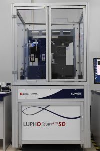
The LUPHOScan system is engineered for carrying out exceptionally precise non-contact 3D measurements on surfaces characterized by rotational symmetry, including aspheric lenses, spherical objects, flat surfaces, and freeform shapes. This cutting-edge system offers several advantages, including rapid measurement capabilities, remarkable adaptability to unconventional surface geometries (such as flat peaks or profiles featuring inflection points), and the capacity to accommodate objects with a maximum diameter of up to 420 mm.
State-of-the-art technology: The LUPHOScan represents an advanced interferometric scanning metrology system, leveraging the cutting-edge MWLI® technology (Multi-Wavelength Interferometry). This MWLI® sensor technology empowers the analysis of diverse surface types, including but not limited to transparent materials, metallic components, and ground surfaces.
Precision Measurement of Varied Surfaces: The MWLI® approach, with its unique capabilities, facilitates the measurement of rough surfaces, including ground lenses. Remarkably, these systems can measure a lens at every stage of its development, from its initial green body to the ultra-precise polished lens, all using the same measuring instrument.
Versatile Analysis of Diverse Shapes: While primarily designed for measuring rotationally symmetric components, these systems can also effectively gauge slightly freeform parts, provided the departure from aspheric, spherical, or flat profiles remains minimal. Notable examples encompass ellipsoidal X-ray mirrors and beam shaping elements.
Empowering Software Modules: The LUPHOSoft software modules are designed to simplify the measurement of intricate and non-continuous optical components. These modules enable 3D form measurements of segmented lenses, annular lenses, axioms, cones, and aspheric-diffractive lenses. Each module is equipped with advanced data analysis tools, supporting a wide range of standard data options, and is compatible with materials testable on LUPHOScan systems.
Reproducibility | Large diameters | Steep slopes | Noise |
Ultra-high accuracy | Up to 420 mm | Up to 90° | Very low noise |
Key Features
- The measurement system is highly versatile, capable of analyzing rotationally symmetric surfaces, including asperse, spheres, flats, and freeform shapes.
- It offers measurement flexibility for a wide range of surfaces, including segmented surfaces, annular optics, rectangular surfaces, surfaces with diffractive structures, and axioms.
- The system provides complete lens characterization (LUPHOSwap), allowing for the measurement of lens thickness, wedge error, decenter error, and lens-mount positioning.
- It can accurately measure large spherical departures and even pancake or gullwing surfaces with points of inflection.
- With the capability to handle object slopes of up to 90 degrees, it is ideal for measuring strong, steep, and small asperse surfaces, including cell phone lens molds.
- The system can accommodate almost every material, whether transparent, specular, opaque, polished, or ground.
- It offers exceptional shot-to-shot stability, with power variation less than ±20 nm (3σ) and PV variation less than ±5 nm (3σ).
- Users can benefit from fast measurement speeds, with a measurement time of 1:45 minutes for a Ø = 30 mm and Roc = 60 mm surface with 100 points/mm^2, and 3:45 minutes for a Ø = 130 mm and Roc = 150 mm surface with 50 points/mm^2.
Key Modifications
- To enhancing the thermal stability of the system, several upgrades were implemented, including the incorporation of more components made of Invar.
- Four temperature sensors and one air pressure sensor were integrated into the system to enable real-time compensation for ambient conditions.
- A more extensive calibration procedure was introduced, taking into account the thermal response of the system.
- The LUPHOSmart sensor control and internal calibration were adapted to ensure precise measurement results.
- Efforts were made to reduce variations in power error determination and improve air flow control.
- The system’s characteristic noise was minimized by implementing tighter manufacturing tolerances.
- Process development on the Precitech Nanoform Diamond Turn machining center contributed to improved assembly.
- Advanced instrument assembly techniques were employed to enhance repeatability and standardize results.
- Additionally, the customer calibration procedure was extended to further improve the system’s performance, particularly in steep slope applications.
Crafted and produced with uncompromising excellence
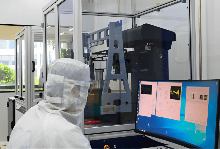
These systems uphold their stability and precision even amidst the harshest environmental challenges, such as demanding manufacturing environments. Thanks to proficiently isolating mechanical impacts and implementing real-time temperature adjustments, these systems assure exceptionally precise and consistent measurement outcomes, even when operating under adverse conditions.

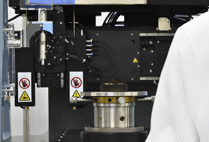
The foundation of each LUPHOScan lies in its Invar reference frame, functioning as an open-loop metrology frame. Utilizing three reference sensors alongside one cylindrical and two plane mirrors, this setup allows for continuous tracking of the object sensor’s position within the frame. Adhering to the Abbe principle, this concept effectively mitigates all primary errors arising from the mechanical R, Z, and T axes.
This reference frame concept, coupled with the extraordinarily high precision of MWLI® sensor technology and an ultra-accurate C stage, ensures a form measurement accuracy surpassing ± 50 nm (2σ) and a reproducibility better than ± 20 nm (2σ).
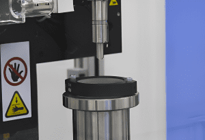
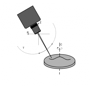
Principle of Measurement:
The scanning procedure is executed through employment of an MWLI® point sensor (multi-wavelength interferometer) in conjunction with four precision stages. The MWLI® point sensor continuously gauges the distance to the surface under examination. Objects undergo rotation via a 360-degree rotary stage (C), while the sensor’s position is regulated by two linear stages (facilitating horizontal (R) and vertical (Z) motions) and one rotary stage (T).
In standard operational mode, the sensor is positioned perpendicular and equidistant to the surface. It is directed to trace the profile of an ideal counterpart of the specimen.
Throughout a measurement, the C stage revolves the object, and the remaining stages maneuver the probe to conduct a spiral scan across the entire surface (refer to figure). The resultant point cloud exposes deviations in shape and any defects on the object’s surface.
WE CAN HELP YOU!
Contact us NOW for sales & expert advice.
