Lens Reverse Engineering Case Study
Case Study: Lens Reverse Engineering

Key Takeaways Reverse Optical Engineering is pivotal for recreating or enhancing optical components, especially when original designs are unavailable or are in need of improvement.  This case study showcases the necessary steps in lens reverse engineering, from customer collaboration and sample testing to optical path simulation and final lens assembly.  Using advanced tools and iterative optimization, tailored solutions meet precise specifications, ensuring customer satisfaction and industry innovation.  The value of reverse engineering extends to revitalizing legacy products and staying abreast of evolving optical industry demands, highlighting its crucial role in technological advancement and customer-centric design. Case Study: Lens Reverse Engineering Introduction Reverse optical engineering, including lens reverse engineering, entails comprehending the functionality of existing optical components or systems through examination.
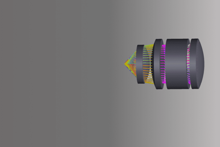
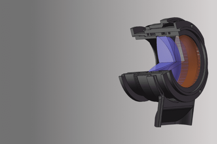
 This facilitates the replication or enhancement of these components. It proves advantageous when the original design is inaccessible or when there’s a desire to enhance existing technology. This method is invaluable for crafting customized optical systems for specific needs, discerning original engineering endeavors, or replicating intricate designs efficiently and cost-effectively. This approach empowers individuals to refine the focal point of an optical system and capture detailed object information for subsequent analysis and manufacturing using the refined design. The traditional design workflow is typically “from scratch”. In reverse engineering, you start with an off-the-shelf machine or component and work backwards to disassemble each component or layer. Due to various reasons, the original manufacturer of this lens has stopped production, but there is still a small amount of demand in the market to continue the production of the lens in reverse. Specification Diameter 32mm Focal length 25mm(magnification 10X) Eye relief 25-250mm   Lens reverse engineering process Customer needs to provide a sample lens  First of all, the customer needs to provide two sample lenses, one for lens image quality testing, and the other for destructive testing of the parameters of the lens and structural components. At the same time, it is also necessary for the customer to provide the use scenario of the lens, so as to pay attention to the customer’s application in the later design. Figure 1 is a customer sample lens. Figure 1. Customer’s sample lens Design optical path simulation  The customer needed an eyepiece with a lens that could achieve a balance between 25-200mm eye relief distance and imaging using a smartphone, and the customer had to be able to look away from the optics and maintain a good image. Key parameters are as follows: Figure 2. Customer Sample Diagram Figure 3. Optical Schematic Diagram Figure 2 and Figure 3 simulate the visual usage of two different lens Settings in existing products. Figure 2 lens does not work for long visual distance, but works well for short visual distance and has high lens resolution. Figure 3 applies to short and long visual distances, but with reduced edge resolution, the distortion is greater when using a smartphone. Retinal image Test the overall parameters of the lens Initially, the primary parameters of the lens undergo testing, encompassing focal length, entrance pupil diameter, back intercept, and image quality. Simultaneously, the lens dimensions are examined, with no alterations made to them during subsequent reverse engineering processes. Disassemble a lens and input the test lens data into the optical design software, such as Zemax. It is necessary to input the test data into the optical design software. If there is any error,  the parameters need to be optimized. Spec Radius Thickness Material Diameter Doublet 50.308 10.488 H-ZK6 32 -22.723 1.477 H-ZF52A 32 -55.444 0.26   32 Singlet 33.006 6.148 H-LAK7A 32 Infinity     32 MTF (modulation transfer function) Test Result Lens overall test results Shorten the lens focal length to 25mm according to customer requirements, and optimize the lens image quality to meet customer requirements. The test results of the newly processed lens are as follows. Assembly and take pictures The actual shot picture is as follows. Lens structure Lens Reverse Engineering Conclusion The process of lens reverse engineering outlined in this case study demonstrates the meticulous steps involved in recreating optical components to meet specific requirements. By combining customer samples, rigorous testing, and advanced design software, we can craft unique solutions even without the original blueprint. Throughout the journey, collaboration with the customer remains paramount. Their input and feedback guide the design process, ensuring that the final product aligns with their needs and expectations. Additionally, iterative testing and optimization guarantee that the lens meets the desired specifications, such as focal length, image quality, and eye relief distance. Ultimately, this case study exemplifies the value of reverse engineering in revitalizing discontinued products or enhancing existing technology. By leveraging reverse engineering techniques, manufacturers can breathe new life into legacy products and consistently address evolving customer demands in the optical industry.  Please contact us if you’d like to request a quote on your next project. Related Content

Read more
Introduction to Reverse Engineering

Key Takeaways Specializing in custom optics, Avantier employs Reverse Optical Engineering (Reverse Engineering) and advanced Manufacturing Capabilities. Non-destructive testing captures precise measurements of test samples. Processed data transforms into high-quality CAD models for analysis and optimization. Strict quality control ensures the accurate replication of components with a focus on meeting specific requirements. Advantages of Reverse Engineering in Creating Custom Optic Systems Reverse optical engineering, also known as reverse engineering in optics, is the process of taking an existing optical component or system, analyzing it, and replicating it to create a similar or improved product. This technique is useful when the original design is not available or when improvements need to be made to an existing product. One of the main benefits of reverse engineering is the ability to create a custom optic system that meets specific requirements. Optic systems are used in a variety of applications, such as medical devices, telecommunications, and military equipment. By reverse engineering an existing system, manufacturers can create custom optics that are tailored to their specific needs. Another benefit is the ability to replicate state-of-the-art optics designs. Optical components and systems can be complex, and creating a design from scratch can be time-consuming and costly. By reverse engineering an existing design, manufacturers can replicate the design more easily and cost-effectively, saving time and money in the process. Reverse Engineering Process Enhancing Optical Systems through Reverse Engineering Capabilities Reverse engineering also allows manufacturers to improve on existing optical systems. For example, they can analyze the design of an existing system and identify areas where improvements can be made, such as reducing chromatic aberration or improving the focal point. By making these improvements, manufacturers can create a more effective and efficient product. In terms of specific capabilities, reverse engineering can replicate a wide range of optical components and systems, including plano concave lenses, cylindrical lenses, and other types of lenses. Manufacturers can also choose from a variety of lens materials, depending on the specific requirements of their application. Reverse engineering relies on a unique set of manufacturing capabilities. One of the key capabilities is the ability to analyze and replicate the behavior of light rays as they pass through an optical system. This requires advanced knowledge of optics design and the ability to use specialized software and equipment. Manufacturing capabilities also include the ability to create complex optical components using a variety of techniques, such as diamond turning and injection molding. These techniques allow manufacturers to create precise components with high levels of accuracy and repeatability. In conclusion, reverse engineering is a valuable technique for creating custom optics and improving existing optical systems. It allows manufacturers to replicate state-of-the-art designs and make improvements to existing systems, resulting in more effective and efficient products. With a unique set of manufacturing capabilities, reverse engineering can replicate a wide range of optical components and systems, providing manufacturers with a cost-effective way to create custom optics that meet their specific requirements. What Avantier does –  At Avantier, we specialize in providing comprehensive reverse engineering solutions for a wide range of industries. With our expertise in reverse engineering techniques and state-of-the-art technology, we offer a reliable and efficient process to recreate and analyze existing objects, components, or systems. Whether you need to replicate a discontinued part, enhance an existing design, or gain a deeper understanding of a product’s functionality, we have the knowledge and capabilities to assist you. What Avantier does in reversing engineering – Test samples: Once received the sample, our engineers will capture precise and detailed measurements of the object or component. This non-destructive process ensures that the original item remains unharmed while providing us with accurate digital data. Model Generation: The collected tested data is then processed and converted into a high-quality computer-aided design (CAD) model or optical drawing. Our skilled engineers utilize industry-leading software to create a drawing representation of the object, capturing its geometry, dimensions, and intricate details. Analysis and Optimization: Once the drawing is generated, we conduct a thorough analysis to understand the component/assembly design. This analysis enables us to identify areas for improvement, optimize the design, and suggest enhancements based on your specific requirements. Prototyping and Manufacturing: With the finalized model, we can proceed to the prototyping and manufacturing phase. Whether you need a functional prototype for testing or a fully manufactured component, we utilize advanced manufacturing technologies to deliver high-quality results. Quality Assurance: Throughout the reverse engineering process, we maintain strict quality control measures to ensure the accuracy and reliability of our work. We employ rigorous inspection methods and validation procedures to verify that the replicated component or system meets your specifications. Please contact us if you’d like to schedule a free consultation or request for quote on your next project. RELATED CONTENT

Read more
How to Read an Optical Drawing

An optical drawing is a detailed plan that allows us to manufacture optical components according to a design and given specifications. When optical designers and engineers come up with a design, they condense it in an optical drawing that can be understood by manufacturers anywhere.  ISO 10110 is the most popular standard for optical drawing. It describes all optical parts in terms of tolerance and geometric dimension. The image below shows the standard format of an optical drawing. Notice thee main fields. The upper third, shown here in blue, is called the drawing field. Under this the green area is known as the table field, and below this the title field or, alternately, the title block (shown here in yellow). Once an optical drawing is completed, it will look something like this: Notice the three fields— the drawing field, the table field, and the title field. We’ll look at each of them in turn. Field I — Drawing Field The drawing field contains a sketch or schematic of the optical component or assembly. In the drawing here, we see key information on surface texture, lens thickness, and lens diameter. P3 means level 3 polished, and describes the surface texture. Surface texture tells us how close to a perfectly flat ideal plane our surface is, and how extensive are the deviations. 63 refers to the lens diameter, the physical measurement of the diameter of the front-most part of the lens 12 refers to the lens thickness, the distance along the optical axis between the two surfaces of the lens After reviewing the drawing field we know this is a polished bi-convex lens, and we know exactly how large and how thick it is. But there is more we need to know before we begin production. To find this additional information, we look at the table field. Field 2— Table Field In our example, the optical component has two optical surfaces, and table field is broken into three subfields. The left subfield refers to the specifications of the left surface, and the right subfield refers to the specifications of the right surface. The middle field refers to the specifications of the material. Surface Specifications: Sometimes designers will indicate “CC” or “CX” after radius of curvature, CC means concave, CX means convex. Material Specifications: 1/ : Bubbles and Inclusions Usually written as 1/AxB where A is the number of allowed bubbles or inclusions in lens B is the length of side of a square in units of mm 2/ : Homogeneity and Striae Usually written as 2/A;B where A is the class number for homogeneity B is the class for striae Field 3: Title Field The last field on an optical drawing is called the title field, and it is here that all the bookkeeping happens. The author of the drawing, the date it was drawn, and the project title will be listed here, along with applicable standards. Often there will also be room for an approval, for a revision count, and for the project company. A final crucial piece of information is the scale: is the drawing done in 1:1, or some other scale? Now you know how to read an optical drawing and where to find the information you’re looking for. If you have any other questions, feel free to contact us!

Read more
Lossless Image Compression Example

For storage and transmission of large image files it is desirable to reduce the file size. For consumer-grade images this is achieved by lossy image compression when image details not very noticeable to humans are discarded. However, for scientific images discarding any image details may not be acceptable. Still, all the images, except completely random ones, do include some redundancy. This permits lossless compression which does decrease image file size while preserving all the image details. The simplest file compression can be achieved by using well-known arithmetic encoding of the image data. Arithmetic encoding compression degree can be calculated using Shannon entropy, which is just minus averaged base 2 Log of probabilities of all the values taken by the image pixels. This Shannon entropy gives averaged number of bits per pixel which is necessary to arithmetically encode the image. If, say, the original image is a monochrome one with 8 bits per pixels, then for completely random image the entropy will be equal to 8. For non-random images the entropy will be less than 8. Let’s consider simple example of NASA infrared image of the Earth, shown here using false color This image is 8-bit monochrome one, and has entropy of 5.85. This means arithmetic encoding can decrease image file size 1.367 times. This is better than nothing but not great. Significant improvement can be achieved by transforming the image. If we would use standard Lossless Wavelet compression (LWT), after one step of the LWT the initial image will be transformed into 4 smaller ones: 3 of these 4 smaller images contain only low pixel values which are not visible on the picture above. Zooming on them saturates top left corner, but makes small details near other corners visible (notice the changed scale on the right): Now the entropy of the top left corner 5.85, which is close to the entropy 5.87 of the complete initial image. The entropies of the other 3 corners are 1.83, 1.82 and 2.82. So, after only one LWT step the lossless compression ratio would be 2.6, which is significantly better than 1.367. Our proprietary adaptive prediction lossless compression algorithm shows small prediction residue for the complete image: Actual lossless compression ratio achieved here is about 4.06. It is remarkable that while the last picture looks quite different from the original NASA image, it does contain all the information necessary to completely recover the initial image. Due to lossless nature of the compression, the last picture, using arithmetic encoding, can be saved to the file 4.06 times smaller than the initial NASA picture file. Our proprietary algorithm applied to this smaller file completely recovers the initial picture, accurately to the last bit. No bit left behind.

Read more
Reverse Optical Engineering Case Studies from Avantier

At Avantier, we are our proud of our track history in assisting customers to solve problems using reverse optical engineering. Here are three case studies. Case Study 1: Reverse Engineering an OFS 20x APO Objective Lens for Bioresearch Genetic engineering requires using precision optics to view and edit the genomes of plants or animals. One world renowned bio research lab has pioneered a new method to speed plant domestication by means of genome editing. While ordinary plant domestication typically requires decades of hard work to produce bigger and better fruit, their methods speed up the process through careful editing of the plants’ genome.  To accomplish this editing, the bio research lab used a high end OFS 20x Mitutoyo APO SL infinity corrected objective lens. The objective lens performed as desired, but there was just one problem. The high energy continuous wave (CW) laser waves involved in the project would damage the sensitive optical lens, causing the objective lens to fail. This became a recurrent problem, and the lab found itself constantly replacing the very expensive objective. It wasn’t long before the cost became untenable. We were approached with the details of this problem and asked if we could design a microscope objective lens with the same long working distance and high numerical aperture performance of the OFS 20x Mitutoyo but with better resistance to laser damage.  The problem was a complex one, but after years of intensive study and focused effort we succeeded in reverse engineering the objective lens and improving the design with a protective coating.  The new objective lens was produced and integrated into the bio research lab’s system. More than three years later, it continues to be used in close proximity to laser beams without any hint of failure or compromised imaging. Case Study 2: Reverse Engineering an OTS 10x Objective Lens for Biomedical Research Fluoresce microscopy is used by a biomedical research company to study embryo cells in a hot, humid incubator.  This company used an OTS Olympic microscope objective lens to view the incubator environment up close and determine the presence, health, and signals of labeled cells, but the objective was failing over time. Constant exposure to temperatures above 37 C and humidity of 70% was causing fungal spores to grow in the research environment and on the microscope objective. These fungal spores, after settling on the cover glass, developed into living organisms that digested the oils and lens coatings. Hydrofluoric acid, produced by the fungi as a waste product, slowly destroyed the lens coating and etched the glass.  The Olympus OTS 10x lens cost several thousand dollars, and this research company soon realized that regular replacement due to fungal growth would cost them far more than they were willing to pay. They approached us to ask if we would reverse engineer an objective that performed in a manner equivalent to the objective they were using, but with a resistance to fungal growth that the original objective did not have.  Our optical and coating engineers worked hard on this problem, and succeeded in producing an equivalent microscope objective with a special protective coating. This microscope lens can be used in humid, warm environments for a long period of time without the damage the Olympus objective sustained.  Case Study 3: Reverse Engineering a High Precision Projection Lens A producer of consumer electronics was designing a home planetarium projector, and found themselves in need of a high precision projection lens that could project an enhanced image. Nothing on the market seemed to suit, and they approached us to ask if we would reverse engineer a high quality lens that exactly fit their needs but is now obsolete.  We were able to study the lens and create our own design for a projector lens with outstanding performance. Not only did this lens exceed our customer’s expectations, it was also affordable to produce and suitable for high volume production.

Read more