Key Takeaways

  • Asymmetric Precision: Standardizing cylindrical lens metrology is crucial for mitigating “smile” distortion and beam steering caused by optical-mechanical axis misalignment.
  • Advanced Centering Protocols: Moving beyond mechanical inspection to laser phase-shift interferometry enables the detection of axial tilt and eccentricity with sub-arc-second resolution.
  • Imaging Quality Assurance: Utilizing Transmitted Wavefront Error (TWE) analysis and focal line characterization to ensure 0.1% EFL precision in high-performance cylindrical optics.
  • Nanoscale Surface Validation: Integrating 3D topography and scattering analysis to quantify cylindricity and surface roughness, essential for high-power laser and AR/VR applications.

Cylindrical lens metrology protocols are essential for bridging the gap between theoretical optical design and high-performance manufacturing. Unlike spherical optics, the inherent asymmetry of cylindrical elements demands specialized measurement techniques to quantify errors in axial tilt, eccentricity, and surface form. As industrial applications in LiDAR, AR/MR/VR, and high-power laser systems push for tighter tolerances, moving beyond basic mechanical inspection toward advanced interferometric characterization is no longer optional—it is a requirement for system-level precision.

Cylindrical Lenses
Cylindrical Lenses
Cylindrical Lenses

I. Quantifying Eccentricity and Axial Tilt

The primary failure mode in cylindrical beam shaping is beam steering or “smile” distortion, caused by misalignment between the optical and mechanical axes.

  • Mechanical vs. Optical Referencing: While mechanical contact measurement (Edge Runout/Edge Thickness Difference) provides a baseline for production, it often fails to account for internal wedge or refractive index inhomogeneities.
  • Laser Phase-Shift Interferometry: By analyzing wavefront aberrations—specifically coma and tilt—it is possible to decouple the rotational error around the axis from X/Y-axis eccentricity. This non-contact approach allows for the calculation of axial tilt with sub-arc-second resolution, ensuring that the “clocking” of the lens is optimized for the final assembly.
  • Differential Absolute Measurement: For high-precision R&D, differential interference measurement (DIM) is utilized to isolate systematic instrument errors. This ensures that the measured surface profile is an absolute representation of the part, independent of the reference mirror’s quality.
Cylindrical lens metrology, Axial tilt measurement, Transmitted Wavefront Error, TWE, Cylindrical lens eccentricity

The three photos above are cylindrical lens eccentricity tests, with high-definition videos and photos available for selection and inclusion in the article.

II.Wavefront Analysis and Focal Line Characterization

In high-power laser applications or fiber coupling, the effective focal length (EFL) is only part of the story. The quality of the focal line is what determines system efficiency.

1. Transmitted Wavefront Error (TWE)

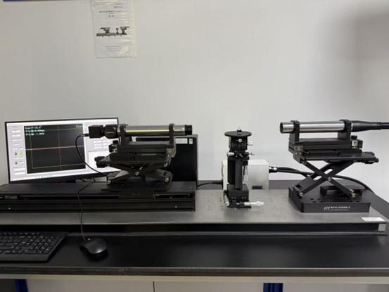
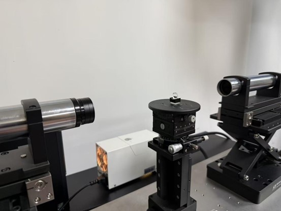
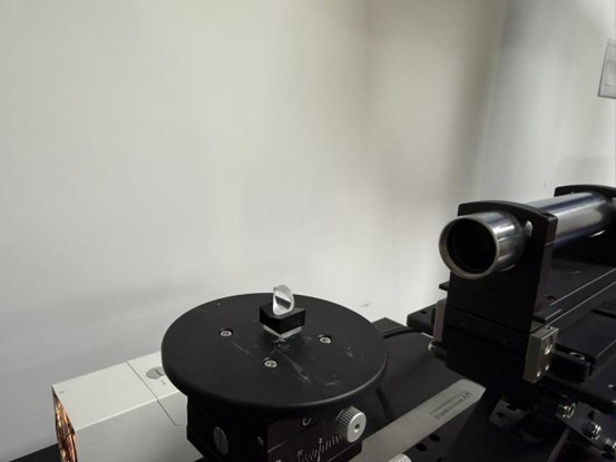
Using a transmission Fresnel laser interferometer, the lens is evaluated for its impact on the wavefront. By quantifying astigmatism and higher-order aberrations, engineers can predict the Strehl ratio of the system. We target an EFL precision of better than 0.1%, which is critical for maintaining beam waist consistency in scanning systems.

2. Line Width and Straightness

For laser line generators, the “straightness” of the focal line is paramount. Specialized collimation and image analysis systems are used to verify the focal line’s position and width across the entire clear aperture, ensuring uniform energy distribution (top-hat profiles) in industrial processing.

III.  Surface Integrity and Sub-Surface Quality

Cylindrical surfaces are notoriously difficult to polish uniformly. High-precision inspection must address both macro-form and micro-roughness.

  • 3D Topography: Utilizing white light interferometers and confocal microscopy, the cylindrical surface is scanned at nanoscale resolution. This quantifies Cylindricity and Straightness, ensuring the surface does not deviate from the ideal geometry.
  • Scattering and Stress Analysis: For coated cylindrical optics, polarization-sensitive imaging and integrating sphere measurements are used to detect coating non-uniformity or internal stress. This is vital for Laser-Induced Damage Threshold (LIDT) assurance, as even microscopic pores can become absorption sites for high-energy pulses.

IV. Conclusion: A Systematic Approach to Quality

The validation of cylindrical optics requires a deep understanding of their asymmetric nature. By integrating interferometric centering, transmitted wavefront analysis, and nanoscale surface profiling, the gap between “designed performance” and “as-built reality” is closed.

Precision in metrology is not merely about having the right equipment; it is about the rigorous application of optical theory to ensure that every asymmetric component performs predictably within complex optical trains.

GREAT ARTICLE!

Share this article to gain insights from your connections!