
Introduction: Adaptive Optics and Wavefront Control in High-Performance Systems
Adaptive optics and wavefront control are fundamental to achieving diffraction-limited performance in modern aerospace optical systems. In applications ranging from space telescopes and ISR payloads to laser communication and directed energy platforms, system performance is ultimately constrained by the ability to measure, predict, and correct wavefront error (WFE) in real time.
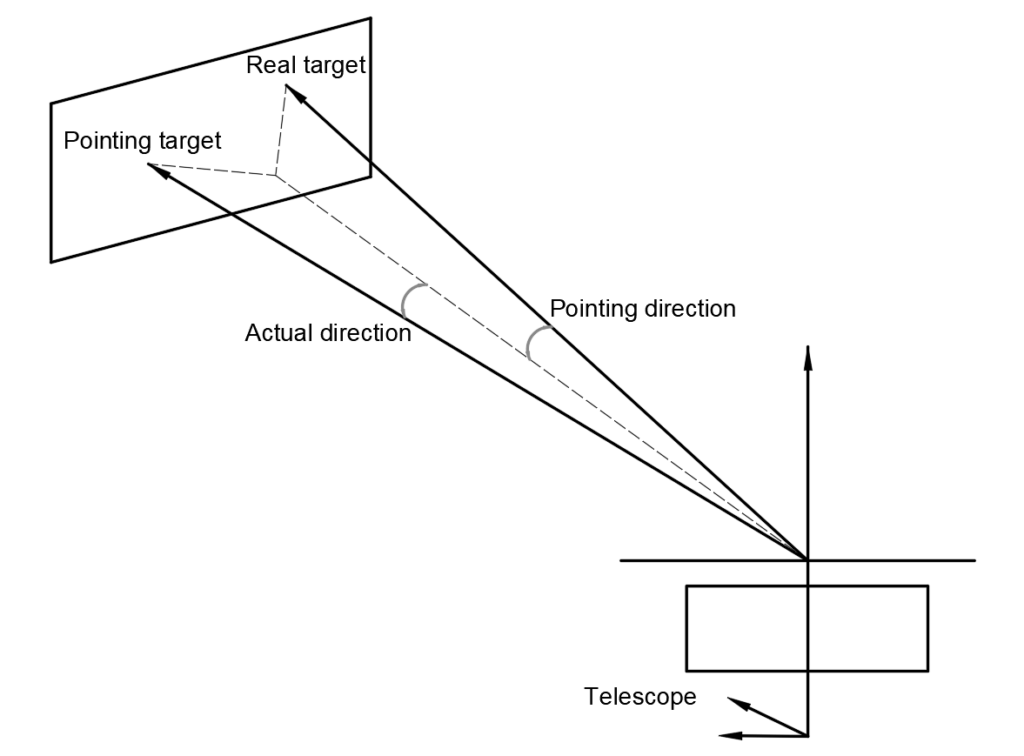
Unlike static optical systems—where wavefront error can be allocated and managed through manufacturing tolerances and alignment budgets—operational environments introduce dynamic disturbances. These include atmospheric turbulence, structural jitter, thermo-elastic deformation, and line-of-sight instability. As a result, wavefront control must evolve from a passive budgeting exercise into an active, closed-loop discipline integrating sensing, control, and correction.
This article builds on prior discussions of wavefront error budgeting in space telescopes and optical design considerations for wavefront sensors, extending them into the domain of adaptive optics (AO) and real-time wavefront control.
Table of Contents
- From Wavefront Error Budgets to Closed-Loop Control
- Adaptive Optics vs Active Optics: Timescale Separation
- Wavefront Sensing as a System Constraint
- The Wavefront Control Problem (Beyond the Textbook Loop)
- Wavefront Error Budget in a Controlled System
- Space-Based Wavefront Control: A Different Regime
- Design Implications for Optical and Mechanical Engineers
- Beyond Classical AO: Predictive and Hybrid Control
- Closing Perspective
1. From Wavefront Error Budgets to Closed-Loop Control
In high-performance optical systems—particularly space telescopes, ISR payloads, and directed-energy platforms—the wavefront is the system. Everything else (MTF, PSF, contrast, pointing stability) is a consequence of how well phase is preserved and controlled.
Your prior article on wavefront error budgets in space telescopes correctly frames the problem at the system level:
- Wavefront error (WFE) is not a single parameter but a budgeted allocation across surfaces, alignment, coatings, and thermo-mechanical effects.
- These contributions combine statistically (often RMS) and must remain within nanometer-level limits for mission success.
However, classical WFE budgeting assumes a quasi-static system. Modern aerospace optical systems increasingly violate that assumption:
- Thermal gradients in orbit
- Structural jitter and reaction wheel disturbances
- Dynamic misalignments in segmented or deployable apertures
- Atmospheric turbulence (for ground-based or airborne systems)
This is where adaptive optics (AO) and wavefront control (WFC) transition from optional enhancement to architectural necessity.
2. Adaptive Optics vs Active Optics: Timescale Separation
A useful distinction (often blurred in system discussions):
- Active optics: compensates low-frequency, large-amplitude errors (seconds scale)
- Adaptive optics: compensates high-frequency, small-amplitude errors (ms scale)
In practice, modern systems combine both:
Domain | Correction Target | Timescale | Typical Actuator |
Active optics | Figure, alignment | ~0.1–1 Hz | Hexapods, mirror supports |
Adaptive optics | Phase perturbations | 100–2000 Hz | Deformable mirrors |
The design implication:
Wavefront control must be partitioned across temporal and spatial frequency domains, not just optical components.
3. Wavefront Sensing as a System Constraint
3.1 Sampling and Spatial Bandwidth
A Shack–Hartmann sensor measures local slopes via centroid displacement across a lenslet array. Implication:- Spatial resolution is limited by lenslet pitch
- High-order aberrations require dense sampling → detector + computation burden
3.2 Photon Budget and SNR
In aerospace scenarios:- Low flux (deep space imaging, long-range laser comms)
- High background (Earth observation, atmospheric scatter)
3.3 Non-Common Path Errors (NCPE)
The sensor does not see the exact same optical path as the science channel:- Beam splitters
- Coatings
- Alignment offsets
4. The Wavefront Control Problem
The canonical AO loop (sense → reconstruct → correct) is well known. The engineering reality is more nuanced.4.1 Reconstruction Is an Ill-Conditioned Problem
Wavefront reconstruction typically involves solving:- Ax = b, where
- b: WFS measurements
- x: actuator commands
- Matrix inversion amplifies noise
- Regularization trades fidelity for stability
- Actuator influence functions are not orthogonal
4.2 Temporal Error Is Often Dominant
Even with perfect spatial correction, servo-lag error can dominate:- Turbulence evolves during measurement + computation delay
- Residual error increases with system latency
4.3 Control Architecture Is Application-Specific
Application |
Control Strategy |
Laser comms |
Beam stabilization + low-order AO |
Directed energy |
High-power, high-bandwidth AO |
Space coronagraphy |
Ultra-stable, nanometer-level WFC |
ISR telescopes |
Hybrid active + adaptive control |
5. Wavefront Error Budget in a Controlled System
Traditional WFE budgets must be extended to include dynamic and control-induced terms:5.1 Decomposition of Residual WFE
Total residual WFE can be expressed conceptually as:- Static optical error
- Alignment error
- Thermal/mechanical drift
- Fitting error (finite actuator density)
- Temporal error (servo lag)
- Measurement noise
- Aliasing error
5.2 Insight for System Designers
A key takeaway for aerospace systems: AO does not eliminate WFE budgets—it redistributes them into controllable and uncontrollable domains.- Manufacturing tolerances → reduced requirements (partially correctable)
- Dynamic disturbances → must be explicitly modeled in control bandwidth
- Sensor noise → becomes a first-order design constraint
6. Space-Based Wavefront Control: A Different Regime
- Tens of picometers RMS wavefront stability for exoplanet coronagraphy
- Long-duration stability over hours
- Phase retrieval + focal-plane sensing
- DM-based “dark hole” generation
- Structural-thermal-optical-performance (STOP) modeling integration
7. Design Implications for Optical and Mechanical Engineers
7.1 Optical Design Is Now Control-Aware
- Optical layouts must consider controllability (DM conjugation planes, pupil mapping)
- Aberration allocation must distinguish between correctable vs non-correctable modes
7.2 Mechanical Design Drives Wavefront Stability
- Structural modes couple directly into WFE
- Thermal gradients → low-order aberrations
- Mounting and bonding strategies → mid/high spatial frequency errors
7.3 Metrology and Calibration Are Continuous
As noted in your WFE budget article:- Interferometry and stitching metrology are foundational But in AO systems:
- Calibration is not a one-time step
- It is embedded into operational control loops
8. Beyond Classical AO: Predictive and Hybrid Control
The field is moving toward:
- Predictive wavefront control (mitigating servo lag)
- Sensor fusion (multiple WFS types, focal-plane sensing)
- Machine learning-assisted reconstruction
- Distributed control across segmented apertures
These approaches reflect a shift:
From correcting wavefront error → managing wavefront dynamics as a stochastic control problem
9. Closing Perspective
For aerospace and defense optical systems, adaptive optics is no longer confined to astronomical telescopes—it is a core systems engineering discipline.
The progression is clear:
- Wavefront error budgeting defines allowable performance (your existing work)
- Wavefront sensing enables observability of phase errors
- Adaptive optics and control provide the means to actively maintain performance
The key shift for modern systems:
The limiting factor is no longer fabrication precision alone—but the integration of optics, structures, sensing, and control into a unified wavefront control architecture.
FAQ: Adaptive Optics and Wavefront Control
What limits adaptive optics performance in aerospace optical systems?
Adaptive optics performance is primarily limited by temporal delay (servo-lag), finite actuator density (fitting error), wavefront sensor noise, and non-common path errors. In dynamic environments, latency and bandwidth constraints often dominate residual wavefront error.What is residual wavefront error in adaptive optics systems?
Residual wavefront error is the remaining phase error after correction and is typically composed of multiple contributors, including fitting error, temporal error, measurement noise, and aliasing. It is commonly expressed in RMS nanometers and directly impacts Strehl ratio and image quality.How do deformable mirrors enable wavefront control?
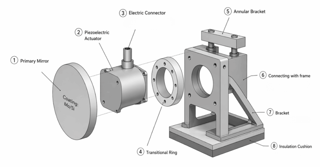
Deformable mirrors (DMs) use arrays of actuators to introduce controlled surface deformations that compensate measured wavefront distortions. Their performance is defined by actuator density, stroke, response bandwidth, and influence function characteristics.What is the role of wavefront sensors in adaptive optics systems?
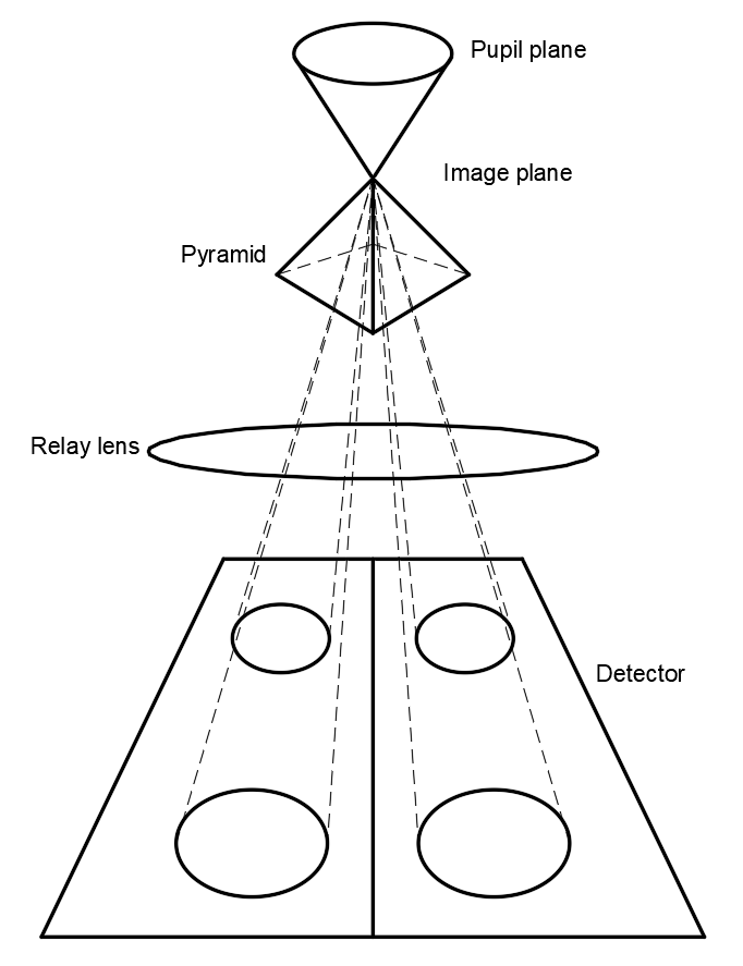
Wavefront sensors provide real-time measurements of phase distortions, enabling reconstruction of the wavefront and computation of corrective commands. Sensor design directly affects spatial resolution, noise sensitivity, and overall control loop performance.How is wavefront error managed in space-based optical systems?
In space systems, wavefront error is dominated by thermal and structural instabilities rather than atmospheric turbulence. Control strategies rely on active optics, deformable mirrors, and focal-plane wavefront sensing to maintain nanometer- to picometer-level stability over long durations.What is the difference between wavefront error budgeting and wavefront control?
Wavefront error budgeting is a predictive, static allocation of allowable errors across system components, while wavefront control is a dynamic, closed-loop process that measures and corrects phase errors in real time. Modern systems require both approaches to achieve and maintain performance.

GREAT ARTICLE!
Share this article to gain insights from your connections!
