

Key Takeaways
- For an ideal, lossless dielectric interface, the magnitude of the TIR reflection coefficient is unity. Practical component throughput remains limited by entrance- and exit-surface Fresnel losses, bulk absorption, surface and subsurface scatter, contamination, and evanescent coupling to adjacent materials.
- Practical TIR design requires the minimum incidence angle—after beam divergence, scan range, fabrication error, and assembly misalignment—to remain above the maximum critical angle across wavelength, temperature, and material-index tolerances.
- Adhesives, coatings, clamps, contamination films, or adjacent optical elements placed within several evanescent decay lengths can couple energy out of the TIR mode. The allowable clearance should therefore be derived from the permitted insertion loss and the refractive index of nearby materials.
- Scatter-limited, high-fluence, and broadband TIR systems may require functional-angle tolerances approaching 5 arcsec, 10-5 scratch-dig, and sub-nanometer RMS roughness. These requirements should be assigned by optical function and verified using explicitly defined datums, apertures, and measurement bandwidths.
Introduction
In practical optical systems, satisfying the nominal critical-angle condition is not sufficient to guarantee low-loss TIR operation. The minimum incidence angle must remain above the maximum critical angle across wavelength, temperature, beam divergence, fabrication error, and assembly misalignment. Surface condition and near-field interaction must also be controlled because defects or adjacent materials within the evanescent decay region can convert an ideal unity-magnitude reflection condition into measurable scatter, coupling loss, or transmission leakage.
This guide presents a worst-case design framework for establishing angular margin, defining TIR-surface specifications, and translating system-level optical requirements into manufacturable prism and waveguide tolerances.
1. Worst-Case Critical-Angle Margin Analysis
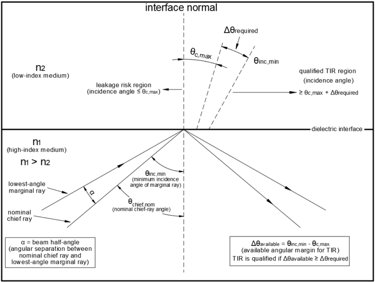
TIR occurs when the incidence angle exceeds the critical angle at an interface where (n1 > n2). For engineering qualification, however, the relevant comparison is between the minimum possible incidence angle and the maximum possible critical angle over the complete operating and tolerance range.
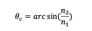
A nominal critical-angle calculation does not establish design compliance. Dispersion, temperature, beam cone, scanning range, prism-angle error, surface wedge, source pointing, and assembly alignment must be combined into a worst-case or statistically justified angular budget.
A. Material, Spectral, and Thermal Index Variation
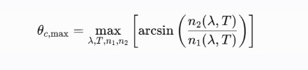
Because the refractive indices of both media vary with wavelength and temperature, the critical angle must be evaluated across the full operating spectrum and environmental range using the applicable refractive-index model or measured material data. For many normally dispersive optical materials, the limiting condition may occur near the long-wavelength end of the band. The maximum value of (θc), however, should be determined numerically over the complete wavelength and temperature range rather than assumed.
Where angular margin is small, catalog refractive-index values should be supplemented by melt data, material-index tolerances, and the refractive-index variation of the external medium.
B. Beam Cone, Scan Range, and Angular Tolerance Stack
In converging, diverging, or scanned beams, the lowest-angle marginal ray—not the nominal chief ray—defines TIR compliance. The calculation must also include tolerance-induced chief-ray shift and beam-pointing variation. The minimum incidence angle should be evaluated after subtracting the beam half-angle, scan excursion, prism-angle error, surface wedge, mounting tilt, and source-pointing error from the nominal chief-ray incidence angle.
Worst-case arithmetic summation is appropriate when TIR failure is unacceptable. RSS or Monte Carlo analysis may be used for statistically controlled production systems, provided that the probability of falling below the required angular margin is explicitly quantified.
The required residual margin should be derived from permitted leakage, polarization sensitivity, manufacturing yield, alignment stability, and environmental range rather than selected as an arbitrary fixed angle.
2. TIR Performance Limits in Precision Optical Systems
A. Precision TIR Prisms & Beam Steering
Right-angle, Porro, and selected penta-prism geometries use TIR to invert, rotate, or displace optical paths without the absorption and environmental durability limitations of many metallic coatings. TIR nevertheless introduces polarization-dependent phase shifts that must be evaluated in coherent and polarization-sensitive systems.- Design Challenge: Surface roughness, subsurface damage, contamination, edge defects, and polishing residue can increase scatter and create localized absorption sites at the TIR interface. Their effect on LIDT depends on wavelength, pulse duration, repetition rate, spot size, pulse count, and test protocol.
- Fabrication Requirement: Scatter-limited, resonant, or high-fluence systems may require TIR-face roughness approaching 1.5 Å RMS and functional-angle tolerances approaching 5 arcsec. The required values should be derived from the system scatter, wavefront, beam-deviation, and damage-threshold budgets rather than applied as universal prism specifications.
- RMS roughness values should be stated together with the measurement method, scan area, spatial-frequency bandwidth, and filtering convention.
- Scratch-dig, RMS roughness, surface figure, and SSD describe different spatial or defect regimes and should not be treated as interchangeable indicators of surface quality.
B. Polarization-Dependent Phase Shift Under TIR
Although the reflection-coefficient magnitude is unity under ideal TIR, the phase shifts of s- and p-polarized components are generally different. Multiple TIR events can therefore introduce accumulated retardance and change the output polarization state without reflected-power loss. For polarization-critical systems, the phase response should be evaluated across incidence-angle, wavelength, and fabrication tolerances. A polarization- and angle-dependent Goos–Hänchen shift also occurs under TIR. It is usually negligible in conventional macroscopic prisms but may become relevant in waveguides, resonant structures, interferometric systems, and repeated-reflection geometries.C. Evanescent-Field Design: TIRF, FTIR, and Near-Field Interference
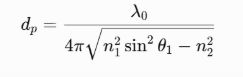
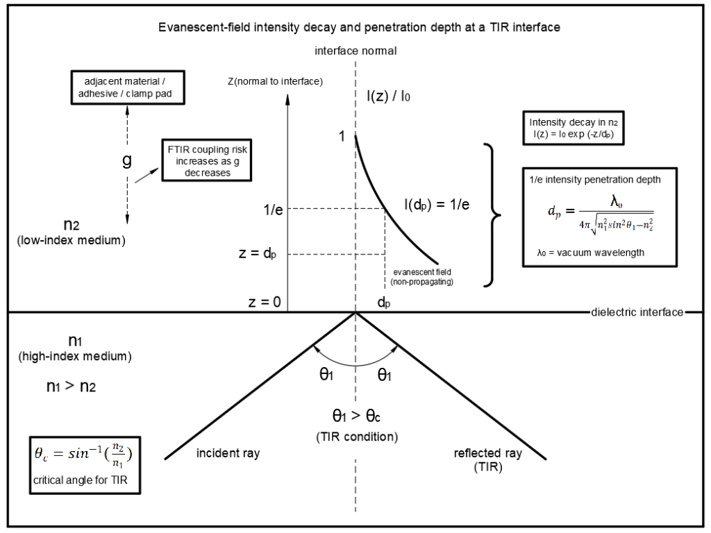
Under TIR, an evanescent field extends into the lower-index medium and decays normal to the interface. Its penetration depth depends on wavelength, refractive indices, incidence angle, polarization, and whether decay is defined for field amplitude or optical intensity.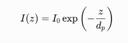
Where the penetration depth (dp) is defined by:
- Total Internal Reflection Fluorescence (TIRF) Microscopy: TIRF can selectively excite fluorophores within a region typically extending from several tens to a few hundred nanometers from the interface. The actual excitation depth must be calculated for the wavelength, refractive indices, incidence angle, polarization, and selected amplitude- or intensity-decay convention.
- Frustrated TIR (FTIR) Touch & Proximity Sensing: A third medium brought within several evanescent decay lengths can couple energy out of the TIR mode. The magnitude of the loss depends on gap thickness, wavelength, polarization, incidence angle, and the complex refractive indices of all participating media.
- For nanometric gaps, multilayer coatings, or absorbing media, a three-layer Fresnel or transfer-matrix model should be used instead of a binary TIR/no-TIR approximation.
- Optomechanical Mounting Hazard: The TIR-face stay-out requirement should specify the permitted clearance, refractive index, thickness, and positional tolerance of nearby adhesives, sealants, clamp pads, protective windows, coatings, and contamination films. Even a low-index intermediate layer may permit tunneling when backed by a higher-index material.
3. Translating System Requirements into TIR Optic Specifications
Custom TIR optics are required when system-level limits on beam deviation, wavefront error, scatter, polarization, environmental stability, or evanescent-field clearance cannot be met by catalog components. Each requirement should be assigned to a functional surface, angle, or datum and paired with an agreed verification method.
| System Requirement | Specification to Define | Typical Verification |
| Beam pointing and deviation | Functional angle, roof-angle error, pyramid error, wedge, and datum-related angular tolerances | Autocollimator or output beam-deviation measurement |
| Wavefront quality | Surface figure, transmitted wavefront error, reflected wavefront contribution, and material homogeneity | Interferometric measurement |
| Low scatter and high contrast | RMS roughness, scratch-dig, subsurface damage, cleanliness, and edge quality | Surface metrology, visual inspection, or scatter testing |
| High-power laser performance | Surface condition, absorption, SSD, edge condition, and LIDT requirements | Application-specific LIDT testing |
| Polarization control | TIR incidence-angle tolerance, accumulated s–p phase retardance, birefringence, and coating response | Polarimetry or ellipsometry |
| Broadband performance | Dispersion, refractive-index tolerance, coating bandwidth, absorption, and angular margin across wavelength | Spectral measurement and wavelength-dependent optical analysis |
| Thermal stability | Thermo-optic behavior, thermal expansion, mount-induced stress, and alignment stability | Thermal cycling and optical measurement over temperature |
| Evanescent-field isolation | TIR-face stay-out distance, nearby material index, coating or adhesive thickness, and contamination limits | Dimensional inspection and FTIR-loss verification |
| Mechanical integration | Datums, clear aperture, thickness, bevels, mounting faces, and positional tolerances | Dimensional and assembled alignment inspection |
| Production repeatability | Process capability, statistical tolerance limits, material variation, and measurement uncertainty | First-article inspection and production capability analysis |
Specifications should be assigned according to the function of each optical surface. The active TIR face may be governed primarily by roughness, scatter, cleanliness, and evanescent-field clearance, whereas entrance and exit faces may be driven by transmitted wavefront error, wedge, coating performance, and ghost suppression.
For ultra-precision optics, each specification should also identify the applicable surface or angle, measurement aperture, datum reference, test wavelength, environmental condition, and allowable measurement uncertainty.
Verification and Metrology Considerations
Specifications should be written together with the verification method. At ultra-precision levels, ambiguity in aperture, datum definition, spatial filtering, test wavelength, or instrument uncertainty may exceed the stated tolerance itself.
Typical verification methods include autocollimator or angle-measuring interferometry for functional angles, phase-shifting interferometry for surface figure, white-light interferometry or AFM for roughness, beam-deviation testing for assembled prism performance, and scatter or LIDT testing under application-relevant conditions.
Engineering Checklist for TIR Qualification
A TIR interface should be considered fully specified only when the design defines the maximum critical angle, minimum incidence angle, residual angular margin, permitted leakage, polarization-phase response, surface and subsurface requirements, near-field clearance, functional datums, and verification methods. These parameters should be evaluated as a connected tolerance system rather than as independent catalog specifications. A surface-quality value or nominal critical angle alone is insufficient to predict system-level TIR performance.
Need a Manufacturable TIR Specification Review?
Share your wavelength range, incidence-angle distribution, material preference, environmental limits, wavefront and scatter budget, required angular margin, and TIR-face clearance constraints. Our engineering team can review manufacturability, datum strategy, surface specifications, and verification methods.






GREAT ARTICLE!
Share this article to gain insights from your connections!