Order | Technical Project | Technical Basis and Experience | Measure of Safeguard |
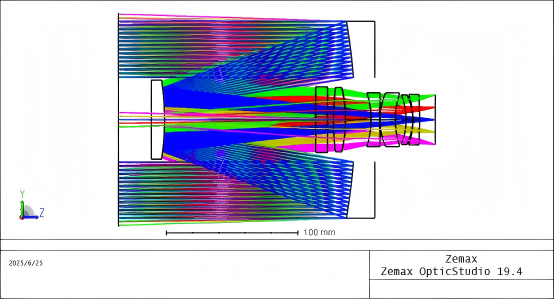
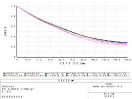
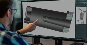
1 | Coaxial Reflective System Design | Multi-model Camera Application | Specialized optical re-optimization |
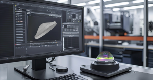
2 | Mirror Machining and Inspection | Legacy of high-precision processing | Multi-set fabrication & metrology equipment |
3 | Space Camera Optical Alignment | 20+ internal system integrations | Dedicated detection and installation facilities |
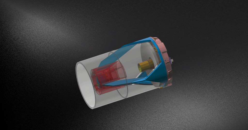
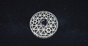
4 | Ultra-lightweight Support Structure | In-house manufacturing excellence | Gravity deformation & aero-thermal investigation |
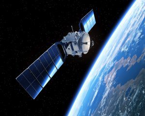
5 | Thermal Focusing | Space-proven camera heritage | Vacuum thermal test verification post-calibration |
6 | Satellite Platform Interface | Multi-model Camera Application | Collaborative engineering with bus structures |
7 | Opto-mechanical Materials | Multi-model Camera Application | Mature design inheritance |