
Off-axis parabolic (OAP) mirrors are indispensable components in modern optical systems, offering precision and versatility in a variety of applications.

Avantier Inc.
Off-axis parabolic (OAP) mirrors are indispensable components in modern optical systems, offering precision and versatility in a variety of applications.

Precision optical polishing refines optical surfaces to achieve exceptional smoothness, accuracy, and clarity, reducing surface defects and light scatter for high-performance imaging, laser, aerospace, and scientific applications.
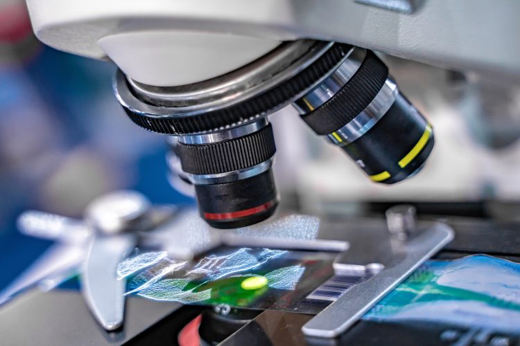
FPM addresses the fundamental trade-off between resolution and field of view in conventional microscopy by combining principles of structured illumination, ptychography, and phase retrieval.

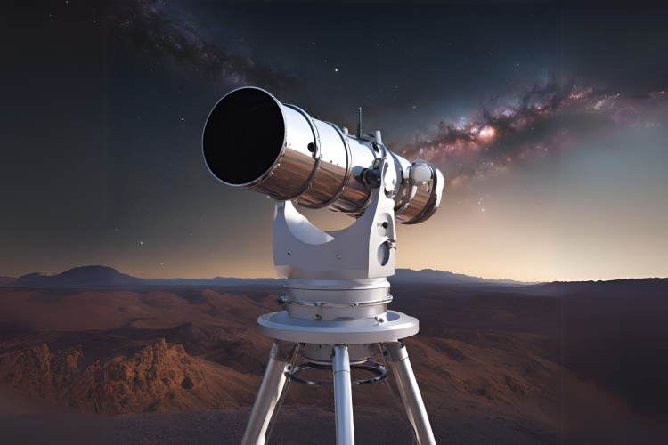
Gravitational wave detection represents one of the most groundbreaking advancements in modern astrophysics, driving the development of highly sophisticated technologies.

Space gravitational wave telescopes are designed to detect minuscule ripples in spacetime caused by gravitational waves. Under harsh space conditions, high precision optical components, radiation-resistant materials, and ultra-stable laser systems are required but also complicate production. Recent solutions in manufacturing, optics and advanced metrology have helped overcome challenges.

Orbital debris poses a very real risk to satellites and orbital spacecraft, and optics debris detection is the most effective way to mitigate that risk.

Quantum photonics is the technology of optics on a quantum level. With applications ranging from quantum information processing to quantum computing and quantum communications
The Ritchey Chrétien (RC) telescope is a highly specialized variant of the Cassegrain reflector telescope, designed to deliver superior optical precision and clarity. Its advanced design minimizes optical aberrations, making it a preferred choice for both space-based and ground-based astronomy.

Adaptive optics is a technology designed to improve the resolution of optical systems that may be affected by environmental factors or the state of the observed object.
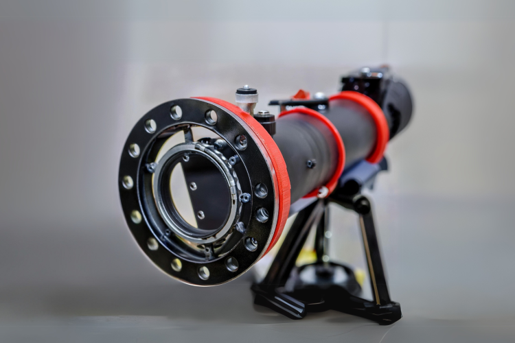
Ritchey Chrétien (RC) telescopes are advanced reflecting telescopes renowned for their exceptional image quality and minimized optical aberrations.
