
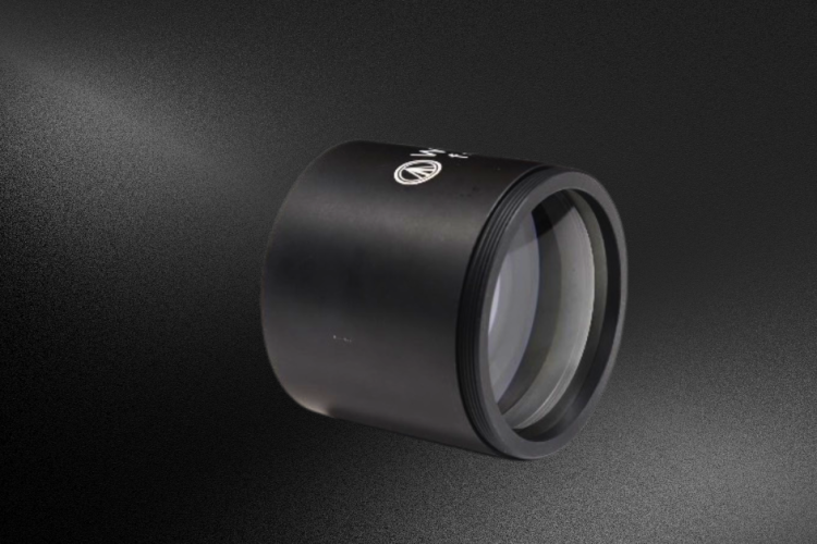
Precision Telecompressors redefine imaging efficiency, pairing full-frame optics with smaller sensors while preserving field of view, sharpening detail, and strengthening low-light performance across advanced applications.
Precision Telecompressors redefine imaging efficiency, pairing full-frame optics with smaller sensors while preserving field of view, sharpening detail, and strengthening low-light performance across advanced applications.

Large-aperture spherical lenses push optical manufacturing to extremes, combining nanometer-level precision with large-scale components to enable high-performance imaging, lithography, and precision metrology systems.
By using optimized materials, negative distortion design, and precision engineering, Wide-band lenses achieve superior imaging quality, ensuring their role as a cornerstone of next-gen optical systems.

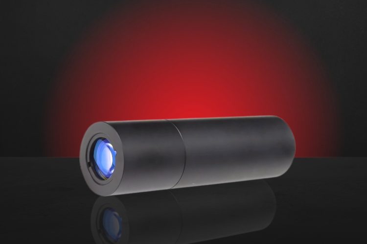
Long working distance objectives enable precise ion control, high-efficiency fluorescence capture, and scalable quantum systems, pushing the limits of optical design in next-gen computing.
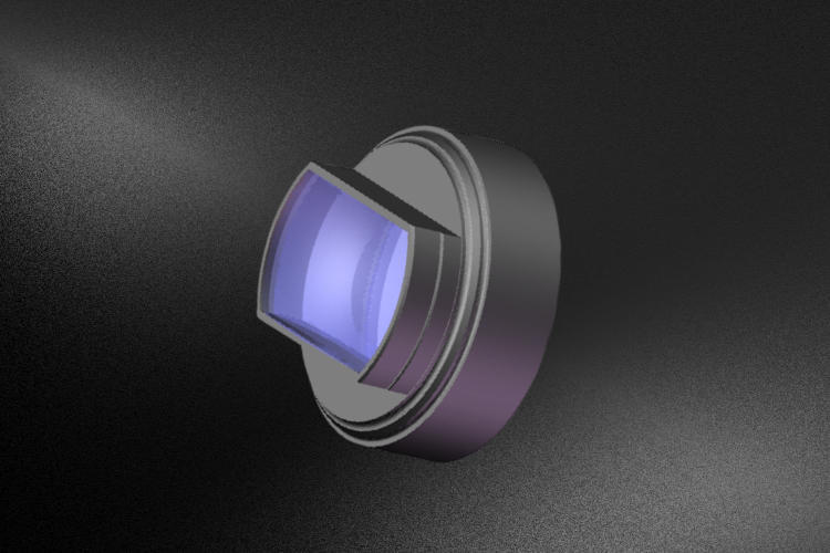
Finite conjugate tube lenses are optimized for fixed-distance imaging, offering precise magnification and strong aberration control. They are ideal for microscopy and inspection but require careful alignment.
Custom high-NA objective lenses achieve ultra-precise UV excitation and imaging in ion trap experiments, boosting fluorescence capture and quantum accuracy.

Laser-Induced Damage Threshold (LIDT) defines the laser energy level that causes permanent optical damage. This guide explains mechanisms, testing methods, and key factors for safe, optimized laser system design.

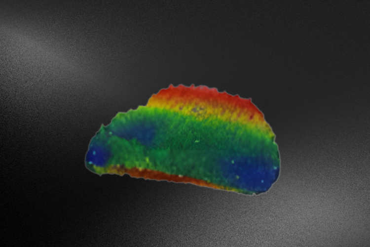
Custom-designed optics enable significant performance enhancements in resolution, sensitivity, and speed in wavefront sensor applications; Key for telescope alignment and interferometer stabilization to advanced imaging and beam-shaping systems.
Star tracker optics enable precise spacecraft navigation, covering lens design types, performance requirements, and face challenges like thermal stability, distortion control, and faint star detection.

The Ritchey Chrétien (RC) telescope is a highly specialized variant of the Cassegrain reflector telescope, designed to deliver superior optical precision and clarity. Its advanced design minimizes optical aberrations, making it a preferred choice for both space-based and ground-based astronomy.