

Key Takeaways
- Large-aperture transmissive optics require system-level control of wavefront error across design, fabrication, alignment, and qualification.
- Broadband performance from 400 to 1000 nm depends on material selection, melt data, thermal behavior, and tolerance allocation.
- For 300–340 mm elements, gravity, fixture loading, mounting stress, and metrology conditions must be treated as optical error sources.
- Final acceptance should be dependent on post-environment wavefront and MTF performance, not dimensional compliance or structural survival alone.
Large-aperture transmissive optics for spaceborne imaging present a tightly coupled engineering problem. Increasing the clear aperture improves light-gathering capability and spatial resolution, but also increases sensitivity to material variation, gravity-induced deformation, mounting stress, alignment error, and temperature change.
For a broadband system operating from 400 to 1000 nm, optical performance cannot be secured by lens design alone. The allocated wavefront-error budget must remain traceable through material procurement, fabrication, coating, integration, alignment, and environmental qualification.
| Parameter | Representative capability |
| Clear aperture | Up to 340 mm |
| Spectral range | 400–1000 nm |
| Surface figure | λ/10 RMS (at 632.8 nm) |
| Average coating reflectance | 0.5% (per surface) |
| Operating temperature | −30°C to +60°C |
| Assembly decenter | Within ±0.05 mm |
| Element tilt | Within ±3 arcmin |
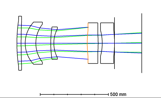
Performance Drivers and Error-Budget Allocation
Development begins by converting mission-level imaging requirements into measurable optical and mechanical allocations. Typical inputs include aperture, wavelength range, field of view, focal length, detector sampling, MTF, allowable wavefront error, operating temperature, launch loads, and mechanical envelope.
These requirements determine how performance is distributed across optical materials, individual surfaces, element spacing, alignment, coatings, and support structures.
For a large-diameter assembly, small mechanical deviations may produce significant optical consequences:
| Error source | Typical optical effect |
| Air-gap error | Spherical aberration and chromatic imbalance |
| Element decenter or tilt | Coma, astigmatism, and boresight shift |
| Retaining force | Surface deformation and wavefront error |
| Temperature variation | Changes in refractive index, geometry, and spacing |
Tolerance allocation must therefore be performed at system level. Monte Carlo analysis evaluates the combined effects of material, fabrication, and assembly variation, while sensitivity analysis identifies the parameters that dominate final image quality.
The resulting errors are divided into three categories:
- errors controlled during fabrication;
- errors corrected during alignment;
- residual errors accepted within the final system budget.
Dimensional tolerances remain important, but final acceptance is dependent on transmitted wavefront and MTF performance rather than dimensional compliance alone.
Planning a large-aperture transmissive payload? Submit your aperture, spectral band, field, and environmental requirements for an initial feasibility review.
Broadband Optical Design and Material Strategy
Broadband correction from 400 to 1000 nm requires deliberate control of primary and secondary chromatic aberration. This is achieved through combinations of high-index lanthanum glass, crown glass, and low-dispersion fluorophosphate materials. Material selection cannot rely only on nominal refractive index and Abbe number. The design must also consider:- melt-to-melt refractive-index variation;
- partial dispersion;
- thermo-optic coefficient;
- coefficient of thermal expansion;
- chemical stability;
- availability and manufacturability at large diameter.
Manufacturing Large-Aperture Optical Elements
Fabrication of a 300–340 mm optical element is dominated by the need to distinguish true surface error from deformation introduced by gravity, fixtures, and measurement conditions. During polishing and metrology, the lens is supported differently from its final flight configuration. Support-point location, clamping force, temperature uniformity, and part orientation can therefore alter the measured surface figure. Finite-element analysis predicts these effects and supports fixture designs that minimize or compensate for deformation. A representative process includes:- material inspection and blank qualification;
- generating, fine grinding, and polishing;
- full-aperture interferometric measurement;
- deterministic surface correction;
- final figure, surface-quality, and datum inspection;
- cleaning and coating.
Assembly, Alignment, and Mounting-Stress Control
Large-aperture integration is a multivariable alignment problem. Element spacing, decenter, tilt, barrel coaxiality, retaining force, and adhesive behavior all affect the assembled wavefront.
A dimensional build alone is rarely sufficient. Before integration, each element is characterized for center thickness, wedge, surface figure, edge geometry, and the relationship between its optical axis and mechanical datums. Engineers then compare these as-built data with the tolerance model.
During alignment, full-aperture wavefront measurements are decomposed into terms such as defocus, spherical aberration, coma, and astigmatism. A sensitivity matrix maps those terms to correctable degrees of freedom, including element decenter, tilt, and axial spacing.
Computer-aided alignment calculates the correction required for the next adjustment, reducing dependence on sequential trial and error. This process also helps distinguish positional errors from surface errors or mounting-induced deformation.
Mount design is equally important. Excessive radial or axial preload can consume a significant portion of the wavefront budget. Spacer geometry, retaining-ring torque, radial clearance, adhesive thickness, curing conditions, and material compatibility must therefore be controlled as optical parameters.
Wavefront measurements before and after retention provide direct evidence of mounting-induced change.
Environmental Verification and Performance Closure
Environmental qualification must demonstrate optical stability, not merely structural survival. A baseline dataset is established before testing and may include:- transmitted wavefront;
- MTF;
- boresight;
- distortion;
- focus position;
- selected mechanical datums.
| Acceptance parameter | Example limit |
| RMS wavefront change | <λ/15 RMS |
| MTF degradation | <5% at (Nyquist frequency) |
| Boresight shift | <5 arcsec |
| Focus displacement | <±50 µm |
Conclusion
Engineering a large-aperture spaceborne transmissive lens is a continuous process of preserving a traceable wavefront-error budget across design, material selection, fabrication, coating, integration, alignment, and environmental verification.
For apertures approaching 340 mm, performance depends on controlling the interaction between optical surfaces, mechanical interfaces, material behavior, and test conditions. System-level tolerance analysis, deterministic manufacturing, wavefront-based alignment, and pre- and post-environment verification provide the closed-loop framework required to deliver stable imaging performance.
Related Content



WE CAN HELP YOU!
Contact us NOW for sales & expert advice.