

Engineering Criteria for Selecting Infrared Lenses
Infrared lens selection should not begin with focal length, F-number, or price.
For experienced engineers, the more useful question is:
Which optical characteristics are actually critical to system performance under the intended operating conditions?
A lens that performs well at room temperature may fail across a wide thermal range. A high-transmission design may still underperform if focus drift, stray light, coating degradation, mechanical decenter, or calibration instability dominates the system.
Conversely, a lower-cost lens may be entirely sufficient when the application does not require long-range discrimination, high-accuracy thermometry, environmental robustness, or wide-temperature stability.
The objective is not to maximize optical performance. It is to apply the minimum optical complexity required to preserve the information the system needs.
1. Start from the system failure mode
Before selecting a lens, define what optical failure would make the system unacceptable. Typical examples include:- insufficient resolution on a distant target
- reduced contrast at low target-background temperature difference
- focus shift over temperature
- degraded off-axis image quality
- unstable radiometric accuracy
- excessive stray light or ghosting
- optical-axis shift under vibration,transmission degradation after environmental exposure
2. Material selection is a system tradeoff
Infrared thermal imaging commonly operates in:- MWIR: 3–5 μm
- LWIR: 8–14 μm
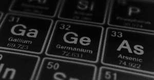
Germanium
Germanium remains widely used in mid-to-high performance LWIR optics.
Optical-grade material typically requires 6N or higher purity, with tight control of defects, impurities, stress, and optical uniformity.
Its penalties are equally important.
Because germanium has a density of approximately 5.32 g/cm³, large-aperture and long-focal-length designs quickly become mass-sensitive. Germanium also has a significant thermo-optic coefficient, making thermal focus shift an important design constraint.
During precision machining, surface figure, roughness, and centration errors can quickly turn into high-value scrap.
The relevant question is not whether germanium is “better,” but whether its optical advantages justify the thermal, mechanical, and manufacturing penalties. 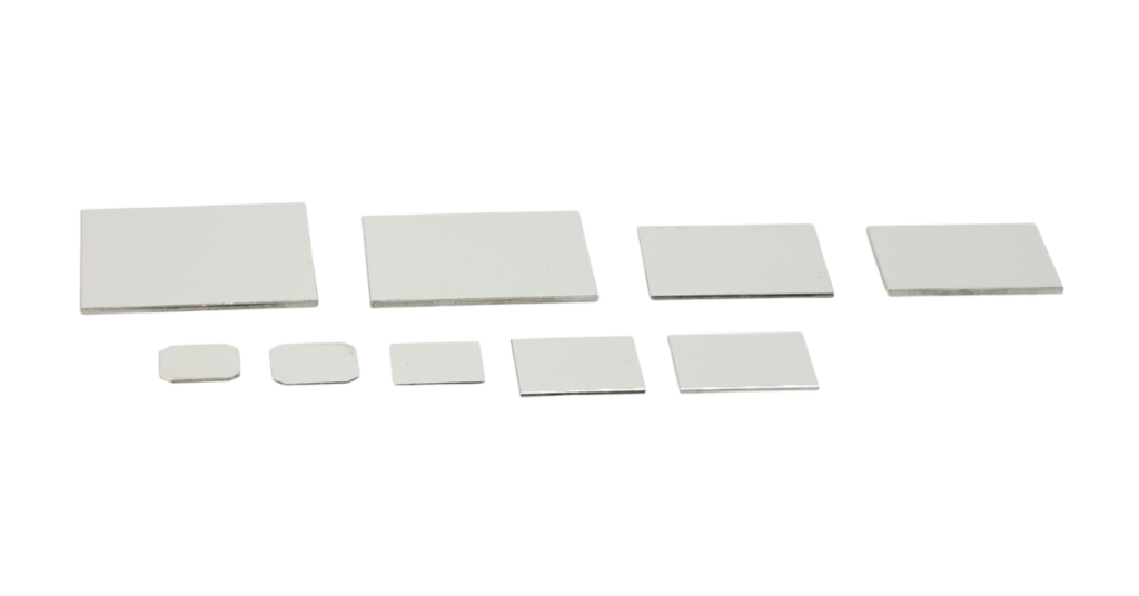
Chalcogenide glass
Chalcogenide glass is attractive where precision molding, lower mass, and scalable production matter. Complex aspheric surfaces can be molded directly, reducing dependence on traditional cutting and polishing processes. However, formulations vary significantly in transmission, thermal stability, mechanical strength, and environmental resistance. Damp heat, salt spray, UV exposure, and impact can also constrain their use in harsh environments. For this reason, higher-performance systems often use multi-material optical designs combining germanium, chalcogenide glass, ZnSe, ZnS, or other substrates.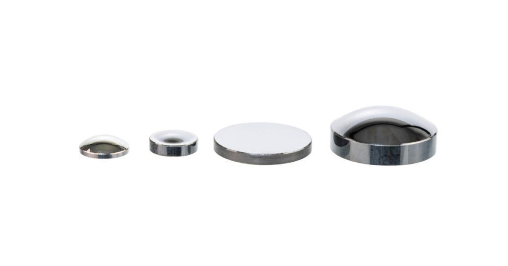
Available materials include:
- Zinc Selenide (ZnSe)
- Calcium Fluoride (CaF₂)
- Zinc Sulfide (ZnS)
- Fused Silica
- Silicon (Si)
- Germanium (Ge)
- Sapphire
- Magnesium Fluoride (MgF₂)
- Chalcogenide Glasses
- Gallium Arsenide (GaAs)
3. F-number should be treated as a system parameter
Reducing F-number increases the infrared energy delivered to the detector and can improve:- NETD
- SNR
- low-temperature-difference discrimination
- image clarity
- radiometric performance
4. Aspheres are useful when they reduce total system complexity
Aspheric surfaces can correct multiple aberrations while reducing element count, track length, mass, and transmission loss.
In infrared systems, however, they may require:
- single-point diamond turning,precision compression molding
- ultra-precision polishing
- individual metrology of surface figure and roughness
The correct question is not whether the design contains aspheres.
It is whether the aspheric surface reduces enough optical complexity to justify the manufacturing complexity it introduces.
For compact or high-aperture infrared designs, it often does.
- Surface figure accuracy: ≤ 0.5 μm PV (form error) for diamond-turned surfaces; ≤ λ/4 @ 633 nm for polished aspheres
- Surface roughness: < 5 nm RMS (diamond turning); < 1 nm RMS (polished)
- Centration error: ≤ 1 arcminute (standard); ≤ 30 arcseconds (precision)
- Diameter range: 5 mm – 300 mm (custom sizes available upon request)
- Materials compatible: Germanium, Silicon, ZnSe, ZnS, Chalcogenide Glass, CaF₂, Fused Silica
Aspheric tolerances are design-dependent. Tighter specifications may be achievable but should be evaluated against manufacturing cost and lead time. Our optical engineering team provides manufacturability feedback during the design review phase.
5. Evaluate performance across the operating envelope
Nominal room-temperature MTF is rarely sufficient for an advanced infrared system.
Performance should be evaluated across the variables that matter to the application:
- field angle
- temperature
- focus state,manufacturing tolerance
- detector sampling
- wavelength band
A design with excellent on-axis MTF may still be unsuitable if edge-field target discrimination is required.
Likewise, a nominally high-performance lens can lose system value if its focus position changes substantially over temperature.
Where possible, lens evaluation should therefore be based on the system operating envelope, not a single nominal optical curve.
MTF specification convention:
- Test wavelength: 10.6 μm (LWIR standard) or 4.0 μm (MWIR standard); custom wavelengths available
- Spatial frequencies: Evaluated at detector Nyquist frequency (e.g., 15 lp/mm for 17 μm pitch, 25 lp/mm for 10 μm pitch)
- Field positions: On-axis (0°), 0.7 field, and full field
- Polarization: Unpolarized (standard); polarization-dependent MTF available upon request
Tolerance methodology:
Monte Carlo tolerance analysis is performed during the design phase
- Standard assembly tolerances: centration ±0.05 mm, tilt ±2 arcmin, air space ±0.05 mm
- Compensators: back focal length adjustment (standard); active alignment available for precision systems
MTF is verified interferometrically and with direct MTF measurement on finished assemblies where required.
6. Athermalization is part of the optical architecture
Temperature changes both refractive index and mechanical geometry.
In infrared systems, especially those using germanium, this can produce substantial focus shifts.
Industrial-grade products may need to operate across approximately -40°C to 80°C.
The main compensation approaches are:
- optical athermalization through material combinations
- mechanical compensation through controlled thermal expansion
- active focusing using motors, piezoelectric elements, and temperature sensors
- software compensation as an auxiliary measure
For system selection, the label “athermal” is not particularly informative by itself.
What matters is:
How much focus shift and MTF degradation remain over the required temperature range?
That should be compared against detector sampling and application-level performance requirements.
7. Coating is a reliability issue as well as a transmission issue
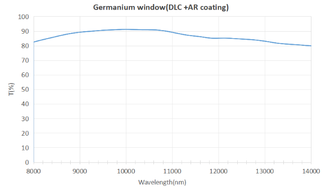
Germanium has a refractive index of approximately 4.0, resulting in more than 30% reflection from a single uncoated surface. AR coating is therefore essential. But infrared coating design may also need to address:- broadband transmission
- out-of-band rejection
- stray-light suppression
- ghost control
- scratch resistance
- damp heat
- salt spray
- sand or dust abrasion
8. Long-range performance is not determined by focal length alone
Long-range imaging depends on more than EFL.
Relevant variables include:
- entrance aperture
- F-number
- detector pixel pitch
- array resolution
- optical MTF
- target size
- target-background thermal contrast
- atmospheric transmission
- vibration
- focus stability
Large-aperture, long-focal-length systems also become mechanically sensitive. Minor alignment errors, structural deformation, or vibration can produce significant image degradation at distance.
Such systems may therefore require tighter alignment, stiffer structures, far-field testing, MTF verification, and temperature cycling.
The useful design question is:
At what range must a target of a given angular size be detected, recognized, or identified with the selected detector and environmental assumptions?
Athermalization performance verification:
- Standard operating temperature range: -40°C to +80°C
- Focus shift over temperature: ≤ 1 × depth of focus (standard); tighter requirements available
- MTF degradation over temperature: ≤ 10% relative to nominal at Nyquist frequency
- Verification method: thermal-vacuum cycling with interferometric or MTF measurement at the specified temperature extremes and spatial frequencies.
9. Continuous zoom should be justified by the mission
Continuous zoom introduces a very different level of system complexity.
The design must maintain acceptable performance while controlling:
- multi-group lens motion
- image-plane stability
- full-range aberration correction
- optical-axis drift
- cam accuracy
- motor control
- dynamic calibration
- thermal stability across zoom states
For a fixed observation geometry, a fixed-focus lens may provide better robustness at lower complexity.
Where the system must transition between wide-area search and narrow-field inspection, continuous zoom may be necessary.
The zoom ratio itself is not the value. The value is whether variable field of view materially improves the operating concept.
| Application Scenario | Recommended Architecture | Rationale |
| Fixed observation geometry, single target distance | Fixed-focus | Minimal complexity, highest robustness, lowest cost |
| Indoor surveillance, short range | Fixed-focus | Temperature variation limited; focus stable |
| Outdoor security, varying target distances | Manual focus or motorized focus | Allows operator adjustment without zoom complexity |
| Wide-area search + narrow-field identification | Continuous zoom (e.g., 4×, 8×) | Enables both situational awareness and target ID |
| UAV/airborne multi-mission | Continuous zoom with active athermalization | Requires full-range performance under vibration and temperature change |
| Thermometry / radiometry | Fixed-focus | Avoids calibration drift introduced by moving groups |
10. Alignment and calibration can dominate real-world performance
Infrared optics can be highly sensitive to lens spacing, centration, coaxiality, and tilt. The more aggressive the aperture, focal length, or zoom architecture, the smaller the available assembly margin. A strong nominal optical design can therefore underperform if manufacturing tolerances are inconsistent with design sensitivity. For radiometric systems, the problem extends further. Lens transmission, self-emission, thermal drift, and distortion can affect temperature measurement accuracy. The lens may need to be calibrated together with the detector, imaging core, and correction algorithms. Calibration can include:- transmission correction
- distortion correction
- temperature-drift compensation
- temperature-measurement deviation correction
When a lower-cost lens is the correct engineering choice
A simpler optical architecture may be entirely sufficient when the application involves:- short working distance
- relatively large targets,
- basic detection rather than identification
- controlled indoor conditions
- limited temperature variation
- no high-accuracy thermometry
- low vibration
- fixed observation geometry
When higher-performance optics become system-critical
More sophisticated optics become justified when several demanding conditions overlap:- long-range small-target detection
- low thermal contrast
- high-accuracy radiometry
- wide operating-temperature range
- automotive or UAV vibration
- outdoor continuous operation
- salt spray, humidity, dust, or abrasion
- demanding edge-field performance
- continuous zoom
- strict optical-axis stability
A practical lens-selection framework
Before selecting a catalog lens, define the following:
Detector
- spectral band
- array format
- pixel pitch
Target
- minimum target size
- observation range
- required detection / recognition / identification level
Optical requirement
- FOV
- EFL
- F-number
- fixed-focus or zoom
- required spatial performance
Radiometry
- imaging only or temperature measurement
- required measurement accuracy
- relevant thermal sensitivity
Environment
- operating-temperature range
- vibration and shock
- humidity
- salt spray
- dust or abrasion
Production
- prototype or volume
- allowable mass and envelope
- unit-cost target
- calibration requirements
A Practical Lens-Selection Framework
For non-trivial infrared systems, a more reliable sequence is:
- define the target and mission conditions
- define the detector
- define angular and thermal performance requirements
- define the environmental envelope
- determine the required aperture, focal length, FOV, and image-quality budget
- determine thermal compensation requirements
- select the material and coating architecture
- evaluate manufacturing and alignment sensitivity
- validate at system level
This process does not always lead to a more expensive lens.
Sometimes a catalog lens is sufficient.
Sometimes relaxing one requirement—FOV, zoom ratio, operating temperature, or radiometric accuracy—substantially simplifies the optical architecture.
And sometimes the combination of long range, small targets, low thermal contrast, wide temperature range, and harsh environments makes high-performance optics unavoidable.
The objective is not to specify the highest-performance lens available.
It is to apply the minimum optical complexity required to preserve the information the system needs.
Related Content

WE CAN HELP YOU!
Contact us NOW for sales & expert advice.