

Aspheric optics can reduce element count, improve aberration correction, and enable more compact optical systems. Their manufacturing difficulty, however, is determined not simply by diameter or material, but by the interaction of aspheric departure, local slope, clear aperture, surface figure, roughness, substrate properties, and metrology strategy.
Avantier manufactures precision aspheric lenses and mirrors using multiple fabrication routes, including CNC generation, deterministic polishing, MRF, ion-beam-based correction, precision molding, and interferometric metrology.
The manufacturing route is selected according to optical performance, geometry, material, production volume, and verification requirements.
Manufacturing Routes for Aspheric Optics
| Manufacturing Route | Best Suited For | Main Advantages | Key Considerations |
| CNC grinding + polishing | Custom glass aspheres, mirrors, low-to-medium volumes | Broad material and geometry flexibility | Longer cycle time; requires iterative metrology |
| CCOS / sub-aperture polishing | Precision figure correction | Deterministic local removal | Tool influence function and edge control |
| MRF | High-precision correction and zonal-error reduction | Highly repeatable local correction | Requires suitable pre-polished surface |
| Ion Beam Figuring | Final non-contact figure correction | Low mechanical loading, deterministic removal | Typically used near final convergence |
| Precision glass molding | Small-to-medium glass lenses, higher volume | High repeatability and lower unit cost at volume | Mold cost, material and geometry constraints |
| Injection molding | High-volume plastic aspheres | Low cost, integration of optical/mechanical features | Thermal stability, shrinkage, birefringence |
| SPDT | IR materials and metals | Direct precision generation | Material dependent |
What Drives Manufacturing Difficulty?
For experienced optical designers, the most important manufacturability variables are typically:
| Design Parameter | Manufacturing Impact |
| Maximum aspheric departure | Drives generation depth, polishing time, and metrology complexity |
| Maximum local slope | Affects tool access, polishing stability, and null-test design |
| Clear aperture | Determines usable processing margin and edge-control difficulty |
| Surface figure tolerance | Determines required correction loop and metrology accuracy |
| Mid-spatial-frequency requirement | Influences polishing process and correction-tool selection |
| Surface roughness | Drives final polishing strategy and scattering performance |
| Substrate material | Affects grinding behavior, removal function, thermal stability, and coating response |
| Mechanical datum scheme | Influences centration, mounting, and test repeatability |
Two aspheres with similar diameter can therefore require substantially different manufacturing processes.
Precision Generation and Polishing
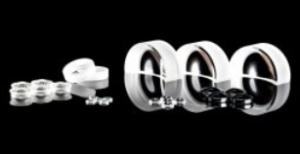
High-precision glass aspheres and mirrors generally begin with CNC generation followed by progressively finer polishing and correction.
Available generation and polishing methods include:
- CNC grinding
- Small-tool polishing
- Computer-Controlled Optical Surfacing (CCOS)
- Magnetorheological Finishing (MRF)
- Ion Beam Figuring / polishing
- Single-point diamond turning for suitable materials
The objective of the generation stage is to establish the required geometry while controlling subsurface damage and leaving a predictable surface for subsequent polishing.
Typical Generation Capability
| Parameter | Capability |
| Diameter range | 5–200 mm |
| Generated surface figure | 0.06 μm PV |
| Ground surface roughness | Ra 0.003–0.005 μm |
| Maximum local slope | Typical Slope Error 1μm – 0.15μm per 1mm window |
Closed-Loop Figure Correction
High-precision aspheric fabrication is performed through repeated measurement–correction cycles rather than a single polishing step.
The core process is:
Measure → Error Map → Removal Calculation → Deterministic Correction → Re-measure
Process convergence depends on:
- Removal-function stability
- Dwell-time accuracy
- Tool condition
- Thermal stability
- Edge behavior
- Test alignment
- Part support during measurement
MRF and ion-beam-based processes are used where appropriate for localized or final correction.
Typical Precision Finishing Capability
| Parameter | Capability |
| Surface figure after deterministic correction | 3μm PV – <0.06μm PV |
| Surface roughness | Ra 0.003–0.005μm |
Aspheric Metrology
For high-precision aspheres, the measurement strategy should be defined together with the manufacturing process.
Depending on geometry and departure, available methods include:
- Full-aperture interferometry
- Refractive null-corrector testing
- Computer-generated hologram (CGH) testing
- Profilometry
- Multi-profile surface characterization
- Non-contact interferometric microscopy
For substantial aspheric departure, a dedicated null system is generally required to convert the nominal reflected wavefront into a measurable reference condition.
Interferometric Capability
| Parameter | Capability |
| Maximum test aperture | 0.4-600 mm |
| Reference wavelength | 632.8nm |
| Surface figure capability | <0.06μm PV |
When specifying or reviewing interferometric results, the following should be explicitly defined:
PV or RMS · surface figure or wavefront error · reference wavelength · evaluated aperture · removed terms · support configuration · measurement uncertainty
Aspheric Lenses vs. Aspheric Mirrors
The underlying correction process is similar, but the engineering priorities differ.| Aspheric Lenses | Aspheric Mirrors | |
| Primary concern | Surface figure plus transmitted wavefront | Reflective surface figure |
| Additional tolerances | Center thickness, wedge, centration | Mounting sensitivity, substrate stability |
| Material considerations | Refractive index, homogeneity, dispersion | CTE, stiffness, lightweighting |
| Coating impact | Transmission and wavefront | Reflectivity and coating-induced figure change |
| Final verification | Surface / transmitted wavefront | Surface figure, often after coating |
Typical Mirror Capability
| Parameter | Capability |
| Maximum mirror diameter | Φ10 – 2000 mm |
| Surface figure | RMS ≤ 1/200λ (λ=632.8nm) |
| Surface roughness | 0.2 nm RMS |
| Clear aperture | ≥90% |
Case Example: High-Precision Aspheric Mirror for Aerospace Optics
For a high-precision aerospace optical system, Avantier manufactured a concave aspheric mirror using a low-expansion Zerodur glass-ceramic substrate. The manufacturing process combined precision surface generation, iterative figure correction, and full-aperture interferometric verification. The finished reflective surface achieved a surface figure error of PV < λ/8 at 632.8 nm across the effective optical aperture, with final figure verification performed after coating. Multi-profile measurements were also used to characterize the aspheric surface at multiple azimuthal positions.
The mirror was finished with a broadband protected-silver reflective coating for visible-to-near-infrared operation. Final verification included surface figure, surface roughness, spectral reflectivity, dimensional characteristics, and aspheric profile data. This example illustrates an important aspect of precision aspheric mirror manufacturing: surface generation, metrology, coating, and final acceptance must be treated as one closed-loop process, particularly when the optical surface must remain within specification in its delivered, coated condition.
Precision Molding for Aspheric Lenses
For production quantities where individually polished optics are not economical, precision molding can provide a more efficient manufacturing route.
Precision Glass Molding
Best suited for:
- Smaller glass aspheric lenses
- Repeat production
- Stable optical prescriptions
- Applications where tooling investment can be distributed across volume
Plastic Injection Molding
Best suited for:
- High-volume production
- Lightweight optical assemblies
- Integrated opto-mechanical components
Optical designers should account for polymer-specific effects including shrinkage, thermal expansion, moisture sensitivity, and birefringence.
Coating and Post-Coating Verification
Coating performance and optical figure cannot always be treated independently.
For precision mirrors in particular, coating stress may alter final surface figure. Where required, final verification can therefore be performed after coating.
Available coating types may include:
- Broadband anti-reflection coatings
- High-reflectance dielectric coatings
- Protected silver
- Aluminum-based reflective coatings
- Ion Beam Sputtered multilayer coatings
- Customer-specific coatings
Typical Coating Capability
| Parameter | Capability |
| Spectral range | UV、Visible、NIR、SWIR、MWIR、LWIR |
| Reflectivity | According to the actual requirements |
Post-coating verification may include surface figure, spectral performance, roughness, cosmetic inspection, and dimensional verification.
DFM Considerations for Aspheric Optics
For demanding aspheres, manufacturing risk is usually reduced most effectively during the optical design stage. Key DFM questions include:| Design Question | Why It Matters |
| Can maximum departure or slope be reduced? | May simplify generation, polishing, and testing |
| Is sufficient margin provided outside the clear aperture? | Helps control edge roll-off |
| Is the specified figure tolerance actually required? | Directly affects correction cycle and cost |
| Can the surface be measured with available metrology? | A manufacturable surface is not useful if it cannot be verified |
| Are mechanical datums compatible with optical alignment? | Affects centration and repeatability |
| Could coating stress affect final performance? | May require pre/post-coating comparison |
| Are roughness and mid-spatial-frequency requirements separately defined? | Different processes may control each error band |
Manufacturing Capability Summary
| Capability | Typical Range |
| Aspheric lenses | Ø 5 – 200 mm |
| Aspheric mirrors | Ø 10 – 2000 mm |
| Surface figure | 3μm PV – <0.06μm PV |
| Surface roughness | Ra 0.003–0.005μm |
| Slope error | 1μm – 0.15μm per 1mm window |
| Centering | 3 arcmin – 0.5 arcmin |
| Surface quality | 80-50、40-20、10-5 |
| Clear aperture | ≥90% |
| Supported materials | Microcrystalline glass, fused silica, silicon carbide (SiC), single-crystal silicon, aluminium, Zerodur, H-K9L, etc. |
Manufacturing Equipment
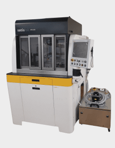
Avantier uses precision grinding and polishing equipment including the Satisloh SPS-200 platform.
Current published working range includes:
| Geometry | Working Range |
| Spherical optics | Ø 10–200 mm, larger sizes subject to configuration |
| Aspheric optics | Up to Ø 300 mm |
| Supported geometries | Spheres, aspheres, cylinders, toroids, freeforms |
Additional manufacturing and metrology equipment:
- Satisloh SPS-200: Precision polishing system; processing range: 5–200 mm (spherical), 10–300 mm (aspherical)
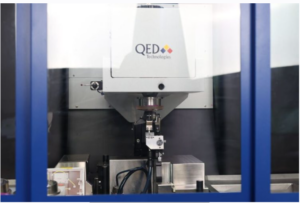
- Q-flex 300 MRF™: Magnetorheological Finishing (MRF) system
- Nanotech 250 UPL: Single-Point Diamond Turning (SPDT) machine
- KERN EVO: CNC machining centre
- Sidai SPCM-M1: Precision cutting system
- Sub-aperture Stitching Interferometer (SSI): High-precision surface figure metrology
Machine capacity alone does not define achievable optical performance. Final capability depends on the complete process chain, including tooling, surface correction, metrology, support conditions, and process stability.
Choosing the Manufacturing Route
The practical question for an optical designer is not simply whether an asphere can be manufactured.
It is:
Which combination of fabrication, correction, and metrology achieves the required performance with acceptable cost, risk, and repeatability?
A molded production lens, a custom high-departure glass asphere, and a precision reflective mirror may all be described as aspheric optics, but each requires a fundamentally different process strategy.
Avantier supports DFM review for aspheric lenses and mirrors, including manufacturing-route selection, tolerance assessment, metrology planning, and coating considerations.
For feasibility review, provide the optical prescription, material, clear aperture, maximum aspheric departure, surface figure, roughness, mechanical datums, and coating requirements.


WE CAN HELP YOU!
Contact us NOW for sales & expert advice.