

Zinc Sulfide Infrared Windows for Space Systems
- Infrared windows used in space systems must do more than transmit light.
- They may also need to withstand thermal cycling, vibration, pressure changes, particle impact, radiation, contamination, rain, sand, or repeated cleaning. At the same time, they must preserve the signal quality required by the detector behind them.
- Zinc sulfide, or ZnS, is widely considered for infrared windows because it offers a useful balance of spectral transmission, optical quality, mechanical performance, and manufacturability. However, selecting ZnS is only the beginning. The final performance depends on the material grade, window geometry, surface quality, coating design, mounting method, and qualification conditions.
- This article explains where ZnS performs well, where it needs additional protection, and what should be considered when specifying a coated infrared window for an aerospace or space application.
Why Use ZnS for an Infrared Window?
ZnS can support a broad range of optical systems, including:
- Mid-wave infrared imaging
- Long-wave infrared imaging
- Multispectral sensing
- Airborne electro-optical systems
- Spaceborne remote-sensing instruments
- Guidance, tracking, and detection systems
Depending on the material grade and processing method, ZnS may provide useful transmission from approximately 0.4 µm to 14 µmµm.
This makes it attractive for systems that need to combine several spectral channels behind one external aperture. A single window can simplify packaging, reduce the number of optical interfaces, and support a more compact sensor design.
ZnS can also be manufactured in planar, curved, domed, spherical, or aspherical geometries. This flexibility is important because aerospace windows are often shaped by both optical and aerodynamic requirements.
The Main Design Challenge: ZnS Is Not a Complete Solution by Itself
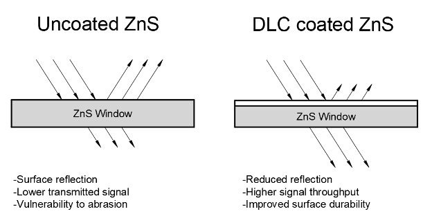
An uncoated ZnS window presents two common challenges.Reflection Loss
ZnS has a relatively high refractive index. Without an antireflection coating, a significant portion of the incoming signal can be reflected at the front and rear surfaces. For a refractive index of approximately 2.2 at 10 µm , the reflection loss may be approximately 14% per surface. In a low-signal infrared system, that loss can directly affect:- Detection range
- Signal-to-noise ratio
- Image contrast
- Radiometric accuracy
- System sensitivity
Surface Damage
ZnS is also more vulnerable to abrasion and erosion than very hard optical materials. This becomes important when the external surface is exposed to:- Rain
- Sand
- Dust
- Ice particles
- Cleaning
- Handling
- High-speed airflow
What Does a DLC Coating Add?
Diamond-like carbon, or DLC, is commonly used as a durable outer coating for infrared optics.
Its primary purpose is to protect the surface. Depending on the coating structure and deposition method, DLC can improve resistance to abrasion, particle erosion, moisture, salt, and repeated cleaning.
Representative coating hardness may be ~30 GPa to 45 GPa , but hardness alone does not determine whether a coating is suitable.
A reliable coating system must also provide:
- Strong adhesion to ZnS
- Low residual stress
- Stable optical performance
- Resistance to thermal cycling
- Compatibility with the intended environment
- Uniform performance across the clear aperture
For many applications, DLC is used as the protective outer layer of a multilayer coating rather than as a stand-alone optical solution.
DLC and Antireflection Coatings Are Not the Same
A protective coating and an antireflection coating solve different problems. A DLC layer is mainly used to improve durability. An antireflection coating is designed to reduce optical loss within a defined wavelength and angular range. In practice, an aerospace infrared window may use:- A durable DLC-based coating on the exposed surface
- A lower-loss antireflection coating on the internal surface
- A multilayer design combining protection and reflection control
- Different coating structures on each side of the window
What Should Be Specified?
A useful technical discussion should begin with the system requirements, not with a coating name. The following information is especially important:Optical Requirements
- Operating wavelength: 3–5 µm (MWIR) or 8–12 µm (LWIR)
- Minimum transmission: ≥ 85 % (coated)
- Average transmission: ≥ 90 % (coated)
- Angle of incidence: 0° (normal) ± 15°
- Polarization requirements: Unpolarized (or specified)
- Maximum allowable wavefront error: λ/10 @ 10.6 µm
Mechanical Requirements
- Window size:5 mm to 280 mm diameter (or custom)
- Thickness:1 mm to 15 mm (based on aperture)
- Pressure differential: ≥ 1 atm
- Vibration level: MIL STD 810 (random vibration)
- Shock level:MIL STD 810 (mechanical shock)
- Mounting method: Edge clamped or bonded
Environmental Requirements
- Operating temperature: 50 °C to +100 °C
- Thermal-cycle range: 55 °C to +125 °C
- Rain or sand exposure:Per MIL STD 810
- Humidity or salt-fog exposure: Per MIL STD 810
- Radiation dose: 100 krad (Si) total dose
- Atomic oxygen fluence: 5×10²² atoms/cm²
- Mission duration: ≥ 5 years (typical)
Manufacturing Requirements
- Surface figure: λ/10 @ 10.6 µm
- Surface roughness: < 5 nm RMS
- Surface quality: 60 40 S/D (standard) or 20 10 S/D (precision)
- Parallelism or wedge: ≤ 1 arc minute
- Clear aperture: ≥ 90 % of diameter
- Edge treatment: Chamfered or beveled
Why Surface Quality and Mounting Matter
A high-performance coating cannot compensate for poor optical fabrication.
Surface figure, roughness, wedge, edge quality, and subsurface damage can all affect the finished window. The mechanical mount can also introduce stress and distort the transmitted wavefront.
For this reason, the coated component should be evaluated after fabrication and, where relevant, after environmental testing.
Typical verification may include:
- Spectral transmission
- Reflectance
- Transmitted wavefront error
- Surface inspection
- Coating adhesion
- Thermal cycling
- Humidity or salt-fog testing
- Vibration and shock
- Thermal-vacuum exposure
- Radiation or atomic oxygen testing
The qualification plan should reflect the real operating environment rather than rely only on generic material data.
A System-Level Approach
The best ZnS window is not necessarily the one with the highest nominal transmission or the hardest coating. The best design is the one that balances:- Optical performance
- Environmental durability
- Mechanical strength
- Coating stress
- Manufacturing tolerance
- Weight
- Cost
- Mission life
Custom ZnS Windows for Space Applications
We support the development of custom ZnS infrared windows for demanding space environments.
Our capabilities may include:
- ZnS material selection
- Planar, spherical, aspherical, and custom geometries
- Precision polishing
- Low-roughness optical surfaces
- DLC protective coatings
- Infrared antireflection coatings
- Multiband coating designs
- Spectral and dimensional inspection
- Environmental qualification support
Typical project specifications may include:
- Component size: 5 mm to 280 mm[XX] to [XX] mm
- Wavelength range: 0.4 µm to 14 µm (or 8–12 µm)
- Surface figure: λ/10 @ 10.6 µm
- Surface roughness: < 5 nm RMS
- Surface quality: 60‑40 S/D (standard) / 20‑10 S/D (precision)
- Average transmission: > 90 % (coated)
- Operating temperature: ‑50 °C to +100 °C
- Applicable test standard: MIL‑PRF‑13830B (surface) / MIL‑STD‑810 (environment)
The most effective starting point is a discussion of the complete operating environment. From there, we can evaluate the appropriate ZnS grade, component geometry, coating structure, manufacturing tolerances, and test plan.
For broader capabilities, see our Space Engineering, Space Optical Coatings, and Infrared Optics pages.
Conclusion
ZnS is a strong candidate for infrared windows in space systems, but its performance depends on more than the substrate.
Reflection loss, surface durability, coating adhesion, thermal stress, optical fabrication, and mounting must all be considered together.
A well-designed ZnS window is therefore not an off-the-shelf material choice. It is an engineered optical component developed around the wavelength, environment, geometry, and mission requirements of the system.


GREAT ARTICLE!
Share this article to gain insights from your connections!