
Optics for LIDAR and sensing are far more affordable today than they were just ten years ago, and the technology is currently accessible to almost anyone.
Optics for LIDAR and sensing are far more affordable today than they were just ten years ago, and the technology is currently accessible to almost anyone.
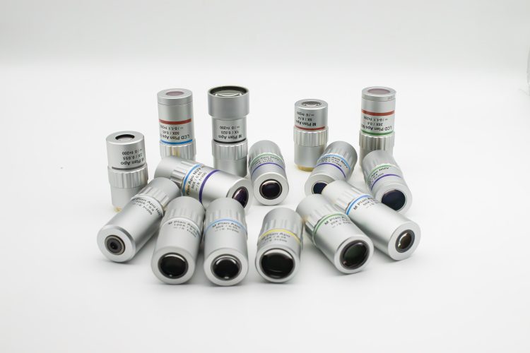
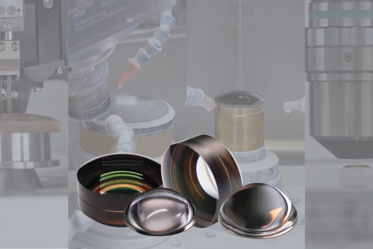
Avantier is a leading expert in crafting high-performance in-stock IR Lenses, and we offer a wide selection of in-stock IR Lenses to meet your needs. These in-stock IR lenses excel in the realm of infrared applications and are invaluable in various industries.
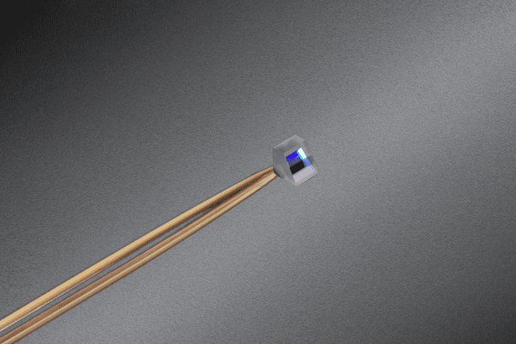
Micro prisms are designed with precision to handle specific wavelengths and coatings, optimizing performance in any optical system.
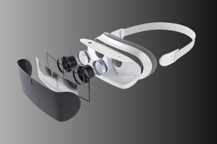
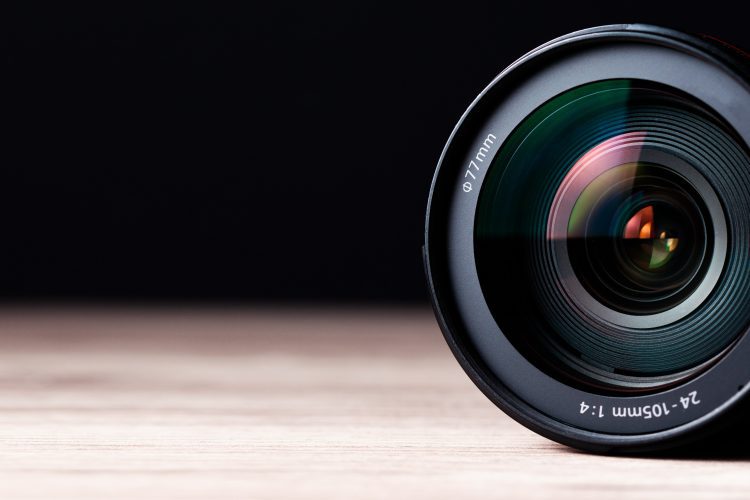
The triplet apochromat lens in VR headsets redefines immersion with minimal chromatic aberration, offering unparalleled clarity and realism.

The guide explains spherical mirrors, the mirror equation, radius of curvature, and contrasts convex and concave mirrors.
One of the most important features of aspheric lenses is their ability to correct for spherical aberration. Spherical aberration is found in all spherical lenses, such as plano-convex or double-convex lens shapes.
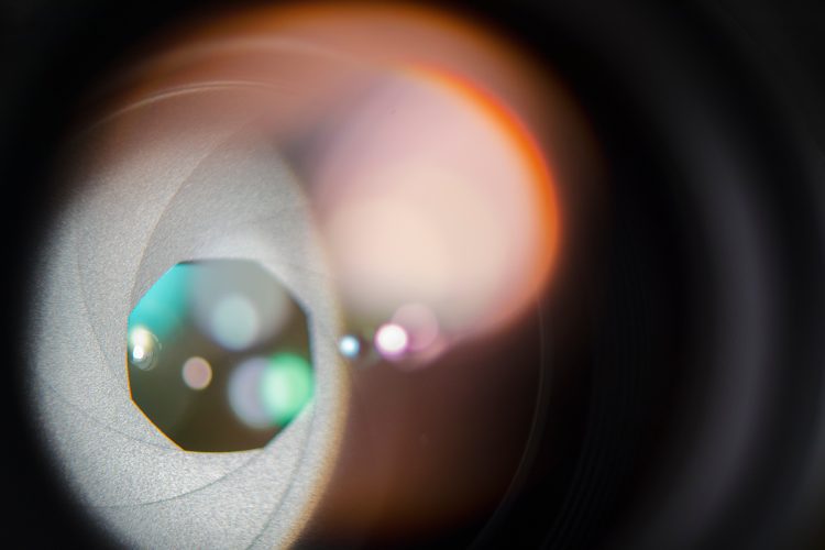
Optimize production with microlens arrays and learn how Avantier encourages clients to articulate specific needs, empowering our teams to seamlessly adapt and drive innovative solutions.
Learn how aspheric lenses revolutionize optical systems by reducing aberrations and enhancing performance, replacing spherical lenses.
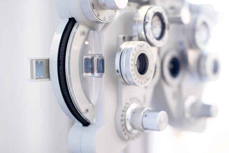
The two-aspheric cemented lens enhances optical performance for ophthalmic examinations, ensuring clear imaging.

Spherical mirrors, including concave and convex mirrors, create real and virtual images by directing parallel rays to or from a focal point.