
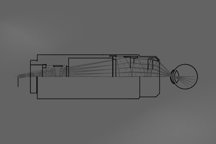
Star tracker optics enable precise spacecraft navigation, covering lens design types, performance requirements, and face challenges like thermal stability, distortion control, and faint star detection.
Star tracker optics enable precise spacecraft navigation, covering lens design types, performance requirements, and face challenges like thermal stability, distortion control, and faint star detection.
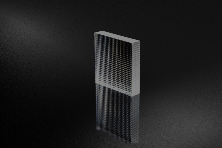
Discover how Avantier’s custom microlens array designs and solutions overcome material and precision challenges, delivering tailored, high-performance solutions for diverse applications.

Diffuse Optical Tomography (DOT) is a medical imaging technique that uses NIR light to measure the optical properties of biological tissue. By analyzing light absorption and scattering from chromophores like hemoglobin, it enables non-invasive, real-time imaging of tissue oxygenation, composition, and functional activity.

Miniaturized optics for satellites and CubeSats are compact, lightweight systems enabling high-resolution imaging, beam steering, and spectral sensing within strict size, power, and mass limits, allowing small satellites to perform advanced, cost-effective space missions.
Discover how Avantier designed long- and zero- distance eye lesion detection lenses for infants and other patients; Optical designers had to consider precision, patient comfortability and helping to innovate future diagnosis techniques.
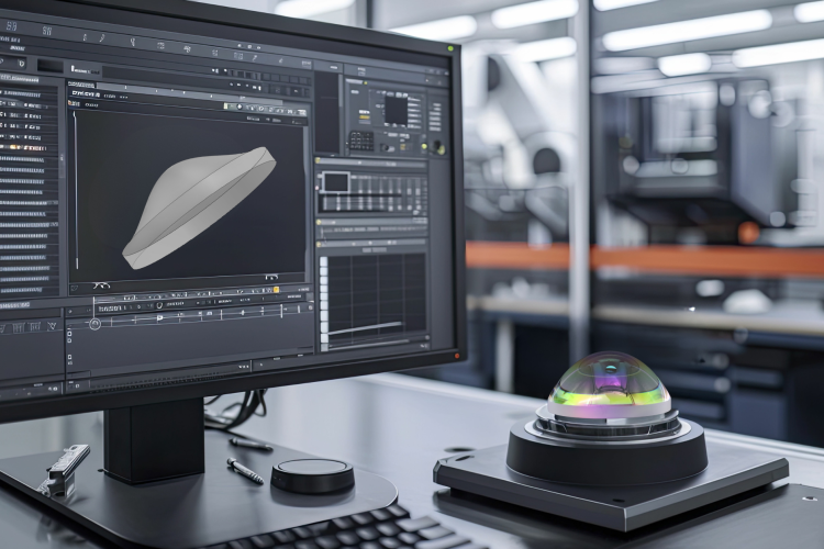
Reverse engineering is one of Avantier’s unqiue capabilities; This process lends itself to technical innovation, IP protection, and rapid, cost-effective replication. Learn about the process of reverse engineering and the advanced tools involved in this aspherical lens case study.
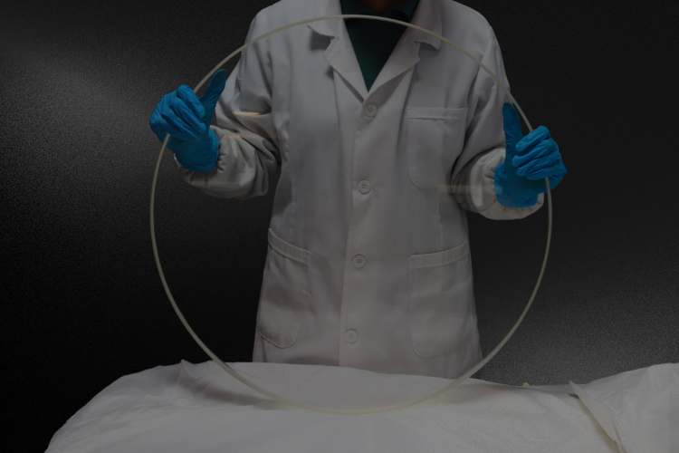
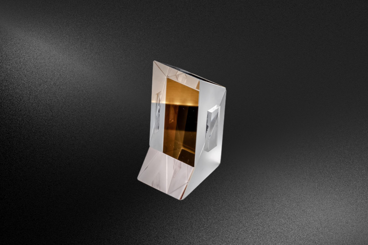
Explore Avantier’s extensive engineering capabilities through large optical components; multiple case studies showcase Avantier’s durable, accurate and stable engineering tailored for various applications.

Optical Communication in Space: From Free-Space Lasers to Deep-Space Data Links
Optical communication in space represents a transformative shift from traditional radio frequency (RF) transmission to high-speed, laser-based data exchange. Using light instead of radio waves, these systems can send vast amounts of data across interplanetary distances with unparalleled efficiency.
Collectively referred to as Free-Space Optical Communication (FSOC), this technology uses modulated laser or LED beams to transmit digital information wirelessly through open space. Within this broad category, space-based laser communications (often called lasercomm) focus on orbital and satellite applications, while Deep Space Optical Communication (DSOC) pushes the frontier even farther—to interplanetary distances.

The intricate anatomy of the ear require specialized optical instruments; Endoscopes offer high-resolution visualization, utilizing advanced optical and illumination systems for detailed examination and surgical assistance. Innovations continue to promise further advances endoscopes, improving diagnostic accuracy and surgical outcomes.
Optical adhesives are used to bond two or more optical elements- lenses, prisms, window pieces can be glued together to achieve various optical functions. This process requires incredible precision, careful alignment of optical components minimizes aberrations and ensures quality.
