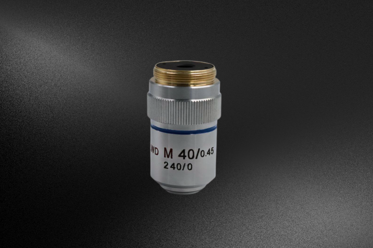
The importance of Ritchey Chrétien telescopes in Space Optics

Key Takeaways Ritchey Chrétien telescopes (RC telescopes) eliminate spherical aberration, coma, and astigmatism, ensuring sharp, distortion-free imaging. Their wide, flat field of view makes them ideal for galaxy mapping, supernova detection, and dark matter studies. Compact, lightweight designs reduce launch costs, while thermal stability ensures reliable performance in extreme conditions. RC systems support advanced instruments for multi-purpose missions. Iconic examples like Hubble and JWST showcase their impact.   The importance of RC telescope in Space Optics In the realm of space exploration, precision is everything. The Ritchey-Chrétien (RC) telescope has become a cornerstone for astronomical instruments, offering exceptional performance through its advanced optical design. Here’s why the RC telescope is pivotal in space optics and what sets it apart. Astrophotography and space-based observations demand unparalleled clarity. The RC telescope excels in eliminating optical aberrations: 1. Aberration Correction Spherical Aberration: RC telescopes are designed to eliminate spherical aberration through the use of hyperbolic primary mirrors and secondary mirrors. This ensures that light from celestial objects converges at a single focal point, enhancing image sharpness. Coma Correction: Unlike simpler telescope designs, such as Newtonian or Cassegrain telescope systems, the RC configuration corrects for coma, which causes off-axis stars to appear distorted or elongated. This is crucial for capturing accurate and uniform data over a wide field of view. Astigmatism Reduction: RC telescopes are designed to minimize astigmatism, further improving the focus and clarity of images across the entire field. This image shows the Ritchey Chrétien telescope with two pieces of flat field lens Example of an F=8.3 Cassegrain telescope, where on-axis performance achieves the diffraction limit, but off-axis aberrations, especially coma, are visible 2. Wide Field of View RC telescopes provide a wide, flat field of view, a critical feature for missions requiring detailed surveys of vast regions of the sky. Applications include: Galaxy Mapping: Capturing high-resolution images of galaxies across the universe. Supernova Detection: Observing transient celestial events. Dark Matter Exploration: Studying cosmic structures influenced by dark matter. 3. Compact and Lightweight Design Space missions are constrained by size and weight due to launch vehicle limitations. The RC design offers a shorter optical tube length compared to other high-performance optical systems, reducing the telescope’s overall size and weight while maintaining high resolution and performance. 4. Thermal Stability in Space Environments Operating under extreme and variable temperatures, space-based telescopes require robust designs. The RC telescope remains thermally stable, minimizing alignment shifts and reducing reliance on complex active adjustment systems. This stability ensures reliable, long-term performance. 5. High Reflectivity and Efficiency RC telescopes use advanced reflective coatings, such as aluminum or enhanced silver, to maximize light collection. This efficiency is crucial for studying: Exoplanets: Observing faint planetary systems around distant stars. Distant Galaxies: Investigating the universe’s most remote structures. Cosmic Background Radiation: Analyzing the remnants of the Big Bang. 6. Seamless Instrument Integration Flexibility is key for multi-purpose missions. The RC telescope’s design allows for easy attachment of advanced instruments such as spectrographs, cameras, and coronagraphs, enabling a wide range of observational techniques. 7. Space Applications RC telescopes play an indispensable role in various astronomical missions: Deep Space Exploration: Imaging distant galaxies and nebulae with unmatched resolution. Exoplanet Research: Supporting precise measurements for photometry and spectroscopy. Astrophysical Phenomena: Studying black holes, gravitational waves, and cosmic microwave background radiation. Deep Space Exploration 8. Iconic Examples of RC Telescopes Hubble Space Telescope: An RC design that has provided some of the most iconic images of the universe with minimal optical distortions. James Webb Space Telescope (JWST): Employing principles of the RC system with deployable optics, it observes infrared wavelengths, pushing the boundaries of what’s possible in space observation. A Telescope Designed for Space’s Challenges The Ritchey Chrétien telescope’s ability to deliver aberration-free, high resolution imaging in a compact and thermally stable form makes it essential for space missions. Whether mapping the cosmos, detecting exoplanets, or exploring astrophysical phenomena, the RC telescope continues to be a driving force in advancing our understanding of the universe. At Avantier, our exceptional engineering knowledge and decades of experience enable us to produce high precision optics, such as SiC mirrors and off-axis parabolic mirrors, for space optics. We provide customized solutions tailored to the unique demands of space-based applications. With top-notch techniques in designing and manufacturing optical lens assemblies, we are committed to supporting groundbreaking advancements in space exploration. Related Content

Read more
Optics for UAVs

Key Takeaways Optics for UAVs must be lightweight, durable, and capable of performing in tough environmental conditions.  Key requirements include balancing size, weight, and power (SWaP), achieving high-resolution imagery from long distances, and enduring temperature and pressure changes.  Thermalized designs help compensate for material expansion, while ruggedized systems withstand vibrations, shocks, and flying particles. UAV optics are critical for various applications, such as vegetation analysis, search and rescue, and industrial inspections, utilizing multispectral, thermal, and machine vision systems for diverse imaging needs. Optics for UAVs must be lightweight and durable, yet offer superior performance even in adverse environmental conditions. These optical assemblies are in many ways the heart of any UAV system, and an unmanned aerial vehicle is only as robust as its machine vision system. Here we’ll look at some of the unique challenges that optics for UAVs must surmount— and the wide range of special imaging capabilities they can bring to an unmanned aerial vehicle. Requirements of Optics for UAVs When designing an optical system for a UAV, an optical designer will need to balance a number of important requirements. Size, weight, and power consumption— sometimes abbreviated as SWaP— are often thought as the big three. Especially when working with small UAVs, every gram directly decreases flight endurance. Weight and size considerations makes continuous zoom a good option, for instance, instead of packing a different lens for every field of view. But there’s more. Optical systems for drones and UAVs must be capable of capturing quality imagery, even from significant distances and under adverse environmental conditions.  Long focal lengths and a good field of view can aid imaging assemblies to produce high resolution images, and special coatings can reduce reflection under strong sunlight.  However UAV optics must also be ruggedized for mechanical shock, vibrations, extreme temperature differences, and pressure changes.  Here we’ll look at the ruggedization requirements for UAV optics. Temperature Changes The refractive index of many substrates depends on temperature, but that’s not the chief worry when it comes to temperature changes and UAV optics. The coefficient of thermal expansion (CTE) of each part must be carefully considered. Glass, metal, and other substrates expand and contract at different rates, and the size of a particular component will be different at different temperatures. Optics for UAVs must be built for the temperature changes they will encounter in the atmosphere. When different materials are used in an assembly, temperature changes can cause lenses to shift, become misaligned, or even crack. A system that will undergo temperature changes must be carefully designed to minimize these issues, compensating for changing sizes when heated or cooled. We call these designs athermalized designs.  Pressure Changes Pressure is another significant issue when it comes to optical systems meant to be used in drones and other aerial vehicles. An assembly designed to have inner and outer chambers at equilibrium when used at ground level will no longer be at equilibrium when outdoor pressure changes. Careful modeling at different pressure values enables optical engineers to design a system that functions well at the low pressures encountered at high altitudes as well as at high-pressure locations.  Mechanical Durability An optical system designed for use within a UAV doesn’t only need to be able to withstand pressure and temperature changes; it also has to be protected against flying particles and ruggedized to withstand vibrations, the shock of quick acceleration changes, and any collusions.  These factors are important to consider when choosing substrates, but it is also important to ensure the final design is as simple and robust as possible, with connections between components reinforced where appropriate.  Optics for UAVs should be designed with carefully sealed components to keep moisture and dust outside. Precise orbital detection of mid-sized debris can also be achieved using carefully designed orbital laser ranging and LIDAR techniques. Often passive optical means and solar illumination are used to first recognize a piece of space debris, which is then illuminated with an intense ns-pulsed TOF laser. The receiver telescope is equipped with single photon detectors, capable of detecting  backscattered photons. This detection method has been used to detect objects of as little as 10 cm in diameter, and typical ranging accuracy is about 3 m rms. Applications of Optics for UAVS The optics you choose for your UAV will depend primarily on your imaging applications and the purpose of the UAV operations. Measurement and control of height above the ground can be accomplished by either active or passive sensing, using machine vision systems that guide the vehicle autonomously at a desired altitude.  For vegetation analysis, high spectral resolution spectrometry, multispectral cameras, or NIR cameras can all provide different imaging capabilities. In search and rescue operations a mixture of RGB and thermal imaging—either short wavelength infrared (SWIR), medium wavelength MWIR, or long wavelength infrared are often used in concert to obtain fail-safe operations under poor environmental conditions. Industrial inspection also often relies on thermal imaging payloads. Optics for UAVs at Avantier At Avantier, we produce custom high-performance optics for UAVs, providing customers in a wide range of fields with the quality optical assemblies they need. Whether you are in industry, surveillance, agriculture or defense, we can work with you to design and produce the optics you need. Contact us today to set up an initial consultation.  References Johnston, C. (2012). Technical challenges for small UAV payloads. Electronic Military and Defense. https://smithmillermoore.com/Pdfs/technicalarticles/7-11_HT_EM&D_TechChallenges_forSmallUAV_Payloads.pdf Srinivasan, M. V., Thurrowgood, S., & Soccol, D. (2006, November). An optical system for guidance of terrain following in UAVs. In 2006 IEEE International conference on video and signal based surveillance (pp. 51-51). IEEE. https://ieeexplore.ieee.org/abstract/document/4020710/ Von Bueren, S. K., Burkart, A., Hueni, A., Rascher, U., Tuohy, M. P., & Yule, I. J. (2015). Deploying four optical UAV-based sensors over grassland: challenges and limitations. Biogeosciences, 12(1), 163-175. https://doi.org/10.5194/bg-12-163-2015 Related content

Read more
How Virtual Reality (VR) Optics Work

Key Takeaways VR optics utilize head-mounted displays (HMDs) to immerse users in virtual environments by projecting virtual scenes through an optical system, reducing eye strain.  Key performance indicators include field of view (FOV) for immersion, EyeBox for comfortable eye movement, distortion control for image accuracy, and dispersion reduction to prevent color fringing.  Optical solutions vary by design: aspherical lenses reduce spherical aberrations, Fresnel lenses are lightweight but can distort images, and Pancake lenses are compact and high-quality but more expensive. An Introduction To VR Optics A head-mounted display (HMD)—commonly referred to as a headset—projects signals from the display screen to the eyes through an optical system, creating a visual experience distinct from reality. Virtual Reality (VR) technology has rapidly advanced, immersing users in entirely virtual environments that feel like another world. At the core of VR display technology lies optical imaging, which projects virtual scenes to users’ eyes, enabling realistic visual experiences. Without an optical system, displays placed too close to the eyes would require constant diopter adjustments, leading to eye strain or damage. Moreover, if the display is closer than the eye’s focal adjustment range, imaging becomes impossible. VR optical systems address this by converting the near-eye display’s point light signals into approximately parallel light rays, minimizing diopter adjustment strain and creating a comfortable, immersive experience.   Early VR optical systems used single lenses, borrowing principles from simple eyepieces like magnifying glasses. However, modern VR systems must balance imaging quality, device size, and weight, leading to the development of specialized optical solutions. Indicators of VR optics Field of view Field of view (FOV) is a critical metric that directly impacts user immersion. FOV refers to the maximum visible area users can see when wearing a headset, defined as the angle between the edges of the field of view. If expressed in the form of an angle, the size of the field of view is the size of the angle between the field of view at the edge of the object and the eye, that is, the maximum visible range, which is called the field of view angle. The field of view angle is an important parameter to judge immersion, which defines the visible area that VR users can see when wearing a headset. A wider field of view allows for a more immersive experience, allowing users to truly be in a virtual environment. In VR optics, 90° FOV is considered to be the pass line for VR immersion experience, 120° FOV is generally considered to be the standard for achieving partial immersive experience, and 180° FOV is the standard for VR to achieve full immersion. Currently, most VR devices offer FOVs between 90° and 120°. EyeBox The EyeBox defines the range within which a user’s eyes can move while still perceiving the image clearly. For a comfortable experience, the EyeBox must accommodate eye movement and variations in user eye spacing. The entry pupil diameter of the human eye is approximately 4 mm, making this the minimum size for the EyeBox. When using VR devices, users usually move their eyes. And each person’s eye distance is different, and the condition of wearing the device is also different when using it. So the EyeBox should be as big as possible. Expanding the EyeBox improves comfort but complicates VR optical design and may impact other performance metrics.   Distortion VR optics transmits the virtual picture to the human eye through the optical system, and the human eye as the entrance pupil is outside the optical system, the system is asymmetric, and due to the large field of view requirements, the optical system often has more obvious distortion. Distortion occurs when the optical system transmits images with geometric inaccuracies, such as “pincushion distortion (pillow distortion),” where images stretch at the edges. Distortion is intrinsic to VR optical systems due to their asymmetrical design and large FOV requirements. Pre-processing images into a “barrel” shape compensates for distortion but reduces resolution. Improved optical designs can alleviate processing demands and enhance quality.  Illustration of Pincushion and Barrel Distortion in VR Optics Dispersion Dispersion is a situation that most VR devices encounter when they are used, manifesting as color fringing, where different wavelengths of light (colors) diverge at the image’s edges. This is because the VR device transmits the signal to the human eye through refraction and transmission, so with the increase of the field of view, the vertical color difference will be more obvious. Off-axis light beam of different wavelengths is focused through the lens after the height of the plane is different, that is, the magnification of each wavelength after imaging is different, so the vertical axis color difference is also called the power color difference. The focal points of multiple wavelengths are sequenced in the direction of the height of the image plane, and the final visible edge of the image plane produces a rainbow band. Lens combinations with differing Abbe coefficients correct chromatic aberrations but increase cost and weight. Image pre-processing is another method to counteract dispersion. Other key indicators in VR optics include resolution, pupil spacing, entry pupil distance, volume, and weight, all of which influence the overall design and usability of the optical system. Optical solutions for VR devices Aspherical lens In theory, near-eye displays can be achieved using a single spherical lens. However, spherical lenses suffer from significant spherical aberration, resulting in poor imaging performance. Additionally, spherical lenses exhibit large field curvature, leading to poor image quality at the edges of the field of view. Spherical lenses also have fewer adjustable parameters, limiting their ability to address these issues effectively. The surface of an aspherical lens is irregular, with curvature that changes depending on the lens’s height. By adjusting aspherical parameters, spherical aberration can be eliminated, and field curvature minimized. This is particularly effective when both lens surfaces are aspherical, offering significantly better imaging quality compared to spherical lenses. Processing aspherical lenses is more complex than spherical lenses. While traditional precision polishing technology offers higher accuracy, it is time-consuming, expensive,

Read more
Mastering Freeform Optics Fabrication

Key Takeaways of Freeform Optics Fabrication Design Complexity: Freeform optics demand advanced modeling tools and exhibit high sensitivity to tolerances. Precision Manufacturing: Specialized techniques like diamond turning and magnetorheological finishing (MRF) ensure quality but are time-intensive and expensive Metrology Advances: Evaluating non-uniform surfaces requires cutting-edge measurement technologies and custom solutions. Cost & Scalability: High prototyping costs and the absence of standardization hinder mass production. Integration Challenges: Alignment sensitivity and material constraints necessitate innovative assembly and robust designs for diverse environments. Freeform optics are custom-designed optical components with irregular surface shapes, enabling precise light manipulation. Unlike traditional symmetric optical components, freeform optics offer unique advantages, such as compactness,  weight reduction, enhanced performance, and tailored functionality. Freeform lens Freeform lens Here’s an in-depth of the challenges associated with freeform optics, categorized into key aspects: 1. Complex Design and Modeling    – Optical Design Software Limitations: Traditional optical design software is primarily tailored to rotationally symmetric systems, lacking advanced features for handling the intricate geometries of freeform surfaces. While software capabilities are improving, challenges persist in ray tracing, wavefront analysis, and optimization.    – Higher Computational Demand: Designing freeform optical components requires substantial computational resources. Techniques like non-sequential ray tracing, genetic algorithms, and machine learning can assist optimization but are resource-intensive and time-consuming.    – Tolerance Sensitivity: Freeform optical designs are more sensitive to manufacturing and alignment tolerances. Even minor deviations can degrade performance significantly, necessitating rigorous design adjustments and stringent tolerance analysis. Different optical elements 2. Manufacturing Precision    – Diamond Turning Challenges: While diamond turning is widely used for freeform optics, achieving precision on non-rotationally symmetric surfaces is difficult. Errors in tool positioning or surface control can result in imperfections that compromise optical quality.    – Limitations in Traditional Polishing: Standard polishing methods for spherical lenses are unsuitable for freeform surfaces. Advanced techniques like MRF and ion-beam figuring are effective but costly, slow, and require skilled operators.    – Replication Issues: Techniques such as injection molding and imprinting can theoretically mass-produce freeform optics, but maintaining high fidelity to the original design and fabrication and achieving low defect rates remain significant challenges. Additionally, replication often faces material constraints, limiting options for applications with stringent optical or environmental requirements. 3. Metrology and Quality Control    – Measurement Complexity: Evaluating freeform optics requires advanced metrology tools, as traditional interferometers struggle with non-symmetric shapes. Optical Coordinate Measuring Machines (CMMs) and multi-axis profilometers often need customization, increasing costs and lead times.    – Non-Uniform Surface Error Analysis: Measuring deviations on freeform optics is more complex than for spherical optics. Metrics like slope error and form error must be calculated across multiple regions, complicating both initial manufacturing and testing quality inspections.    – High-Precision Alignment: Aligning freeform optics in optical systems is more demanding than with traditional lenses. Slight misalignments can introduce significant aberrations, requiring innovative alignment methods and in-situ adjustments. 4. Cost and Scalability    – Prototyping and Testing Costs: Creating prototypes for freeform optics is expensive due to the need for specialized equipment and skilled operators. Iterative design cycles are slower and more costly compared to spherical or aspherical optics.    – Lack of Standardization: Freeform optics often require custom manufacturing processes, limiting opportunities for standardization and economies of scale. As a result, their use is typically restricted to high-end or niche applications.    – Tool Wear and Replacement: Manufacturing freeform surfaces increases wear on tooling, especially in diamond turning. Frequent tool recalibration and replacement further drive up production costs. 5. Alignment and Integration    – Complex Assembly Procedures: Accurate aligning each part can be challenging in imaging systems with multiple freeform components. This often requires custom fixtures and real-time adjustment mechanisms, increasing complexity and potential points of failure.    – Aberration Sensitivity: Freeform optics are used to correct specific aberrations, but any misalignment can reduce correction quality or introduce new aberrations, severely impacting system performance.    – Thermal and Mechanical Stability: Thermal expansion or mechanical stress can shift alignment. Materials with low thermal expansion coefficients and complex mounts are necessary to maintain alignment under operational stresses. 6. Material Limitations    – Optical Material Constraints: Some traditional optical materials, such as certain glasses and polymers, are challenging to shape into freeform surfaces or lack the thermal stability required for precision applications.    – Environmental Requirements: In extreme environments (e.g., aerospace or underwater), freeform optics must be made from materials capable of withstanding temperature fluctuations, humidity, and radiation. These requirements often narrow material options and necessitate specialized coatings.    –  Coating Challenges: Anti-reflective and protective coatings are often applied to freeform optical surfaces. However, achieving uniform coating on non-uniform surfaces like freeform optics can be difficult, potentially affecting optical performance and durability in challenging environments. Freeform Optic Freeform Optic Mastering Freeform Optics Fabrication These challenges highlight the complexities of designing and manufacturing freeform optics. Each stage—from design and prototyping to production and integration—requires advanced tools, precision techniques, and significant investment. However, with ongoing advancements in manufacturing processes, computational design, and metrology, the potential of freeform optics continues to grow. Applications in compact imaging systems, augmented reality, and custom sensor solutions are expanding, making freeform optics a promising frontier in optical innovation. Related Content

Read more
 Adaptive Optics for Microscopy

Key Takeaways Adaptive optics for microscopy improves image quality by correcting refractive aberrations in specimens, especially in deep tissue imaging.  Techniques involve sensors, deformable mirrors (DMs), and spatial light modulators (SLMs) to dynamically counteract distortions. DMs, ideal for broadband light, adjust with electrostatic or piezoelectric forces, while SLMs suit laser-based, wavelength-specific applications. Adaptive optics setups vary by microscope type, as aberration correction needs differ. Customized AO solutions allow users to optimize high resolution imaging for complex optical applications. There’s a promising new way to improve image quality and correct for the inevitable aberrations in high resolution microscopy.  Adaptive optics for microscopy. Choosing high quality optics enables you to improve your image quality and produce high resolution microscope images. But even if you’re working with optical components that are ideal and perfect in every sense, there are some aberrations that won’t go away. These are the aberrations caused by the spatial variations in the refractive index of the specimens being studied. The deeper the tissue being imaged, the worse the problem gets.  Adaptive optics involves a range of techniques that enable you to correct for these aberrations before the image is produced, making high-resolution and even super-resolution imaging possible in tissue as deep as tens or hundreds of micrometers. Here we’ll look at just how adaptive optics work to make high quality microscopy possible even with deep tissue imaging. Understanding Adaptive Optics for Microscopy How can you correct for aberrations caused by inhomogeneous samples and specimens with complex optical structures? The trick is to use optics that can transform themselves based on their environment, adapting on-the-go when faced with specific aberrations.   Dynamic aberration correction involves an optical system that includes a special sensor that measures aberration at different parts of the sample. This might, for instance, be a wavefront sensor. A sequence of measurements is used to optimize the aberration correction, and deformable mirrors (DMs) or liquid spatial light modulators  (SLMs) respond in real-time. These dynamic optics provide conjugate aberrations— equal but opposite—- to cancel out the problematic aberrations at each point on the sample. caption: This series of images demonstrates how adaptive optics for microscopy work to cancel out the aberrations caused by the nonuniform optical profile of the specimen. Choosing the Right Adaptive Optics for Microscopy Adaptive optics can work well in many types of high-resolution microscopes, from fluorescence  and multi-photon fluorescence microscopes to laser scanning microscopes and parallelism scanning systems. But it’s important to realize there’s no one plug-and-play adaptive optical solution that works in any microscope you might want to use. The adaptive system will need to be customized based on both the physical configuration of the microscope and the image formation process that is used.  Suppose you use a conventional wide field fluorescence microscope. In this microscope, the illumination path is used simply to illumine the sample in a uniform way, and aberrations are only a problem when it comes to the imaging path.  In a confocal microscope, however, aberration is problematic in both the illumination and imaging paths, and adaptive optics need to be set up to compensate in both areas.  But those are not the only two possibilities. In a two-photon excitation fluorescence microscope, the resolution is dependent on the illumination path, and it is here you might need adaptive optics: aberrations in the imaging path will have no effect on the final results. When using adaptive optics for microscopy with a confocal microscope, attention must be paid to both illumination and imaging paths. Comparing Adaptive Optic Elements When it comes to the actual optical elements within your AO microscopy system, you have two major options: liquid crystal spatial light modulators or deformable mirrors.  A deformable mirror is a dynamic optic manufactured with a reflective surface. The shape of this surface may be continuous or segmented, but either way is designed in such a way that it can be ‘deformed’ or changed by the application of tens to hundreds of actuators, which are acted upon by either electrostatic, electromagnetic, or piezoelectric forces. Deformable mirrors are polarization independent and typically provide high reflectance over a broadband. DMs are generally the best choice for fluorescence light and other weak emissions, or when multiple wavelengths of light must be corrected simultaneously. A spatial light modulator is wavelength dependent and can only be used with parallel light. There are different types of SLMs, but liquid crystal on silicon (LCOS), used in reflection mode,  is one frequently used option. Most SLMs have lower optical efficiency than DMs, but they are a good choice for many laser applications. There’s also a third possibility, which is not yet widely used in microscopes but may gain importance in the future: transmissive adaptive elements. A transmissive adaptive element is formed of transparent, fluid-filled chambers. The shape of these chambers can be dynamically altered to create the desired aberration. References Booth, M. Adaptive optical microscopy: the ongoing quest for a perfect image. Light: Science and Applications 3, e165 (2014). https://doi.org/10.1038/lsa.2014.46 Marx, V. Microscopy: hello, adaptive optics. Nature Methods 14, 1133–1136 (2017). https://doi.org/10.1038/nmeth.4508 Jingyu Wang, Yongdeng Zhang. 2021: Adaptive optics in super-resolution microscopy. Biophysics Reports, 7(4): 267-279. DOI: 10.52601/bpr.2021.210015 Booth, M. J. (2019). A basic introduction to adaptive optics for microscopy (1.0). Zenodo. https://doi.org/10.5281/zenodo.3471043 Related Content

Read more
Application of Optical Waveguides in AR Glasses

Key Takeaways AR glasses utilize waveguide technology to overlay virtual images onto the real world, creating immersive experiences across sectors like healthcare, manufacturing, and defense.  Optical waveguide designs enable high-quality AR displays, balancing transparency with an expansive field of view.  Key types include geometric and diffracted waveguides, each offering distinct benefits in form factor and image quality.  Total internal reflection (TIR) optimizes light control, making waveguide displays a promising AR solution for blending virtual content with real-world visibility. Introduction to AR Glasses Augmented reality (AR) glasses are advanced devices that integrate waveguide technology to seamlessly blend real-world visuals with computer-generated information, such as images, sounds, and videos. These virtual images are superimposed onto the real environment, providing users with a richer and more immersive experience. AR technology has found applications across various sectors, including defense, industrial manufacturing, healthcare, entertainment, and education, significantly enhancing how people interact with digital information in real-time across diverse professional and personal contexts. AR optics leverage waveguide designs to project display content directly into the user’s line of sight, allowing them to see the physical world while engaging with virtual content. Key components of AR optics include the AR display, the eye, and an optical lens. Unlike virtual reality (VR), which places a display screen directly in front of the user’s eyes, AR glasses position the display near the temple or forehead to avoid obstructing real-world imaging. To ensure a high-quality visual experience, the lens magnifies the image, alters the optical path, and transmits it off-axis to the human eye while maximizing the field of view (FOV). Additionally, the lens must maintain transparency to ensure clear visibility of the real environment. Types of AR Glasses Various optical systems have been explored in AR glasses. The four main optical solutions currently in use include prisms, free-form surfaces, Birdbath optics, and optical waveguides. Prisms: This solution uses semi-transparent and semi-reflective prisms to project images to the eye, allowing users to simultaneously see real and virtual content, creating a blended experience. However, prism-based optics offer limited field of view, restricting their usage scenarios. Free-Form Surface: This approach employs reflective surfaces to project images. A variant, known as Birdbath, uses a polarizing beam splitter to reflect light from a free-form surface to the user’s eye. Though lightweight and cost-effective, it has lower transmittance due to multiple reflections and transmissions, impacting image brightness. Optical Waveguides: Optical waveguides are one of the most promising AR solutions, using total internal reflection (TIR) to transmit light through a glass substrate and deliver the image directly to the human eye. Total Internal Reflection and Optical Waveguides Optical waveguides provide thinness and high transparency, making them ideal for consumer AR applications. These waveguides use a polished glass substrate where light is coupled and retained through total internal reflection. By reflecting multiple times within the glass and then directing it to the human eye, the waveguide achieves off-axis image transmission. Its transparency also allows the real-world signal to reach the user’s eye, seamlessly layering virtual and real images. Total reflection effect Total Internal Reflection (TIR) TIR is a common optical phenomenon. When light passes from a medium of higher density to one of lower density and the angle of incidence exceeds a certain critical angle, the light reflects entirely within the medium. TIR has various applications, including optical fibers, light rods, and prisms that utilize this effect to control light paths. Different types of light guides Types of Optical Waveguides in AR Glasses The AR glasses optical waveguide solution includes a display and an optical lens, using TIR principles within the lens to transmit light. Light is directed into and out of the lens at specific angles, critical for achieving effective TIR. There are two main types of optical waveguides: Geometric Optical Waveguide: Mirrors guide light into the lens through reflection. A semi-reflective mirror outputs the optical signal while preserving real-world light transmission. Although this setup minimizes light loss and provides good imaging, it requires complex coatings and adhesion processes. Diffracted Optical Waveguide: In this approach, a grating structure inputs and outputs light. Gratings direct light efficiently by adjusting structural characteristics like period and depth. There are two main types of diffracted optical waveguides: Surface Relief Waveguide: Utilizes etched or embossed periodic gratings on the glass surface to produce a low-cost but lower-quality imaging solution. Volume Holographic Waveguide: Uses laser interference exposure to create periodic refractive index changes within the material, resulting in high diffraction efficiency and excellent image quality, though with a more complex production process. These different waveguide types offer varying advantages and limitations, yet they continue to drive innovation in consumer AR and display technology.  geometric optical waveguide Diffracted optical waveguide In conclusion, the integration of advanced optical technologies in augmented reality glasses represents a significant leap forward in how we interact with digital content. By effectively merging the virtual and real worlds, AR glasses have the potential to revolutionize various industries and enhance everyday experiences. As this technology continues to evolve, ongoing innovations in optical waveguides and other optical solutions will play a crucial role in refining the performance and usability of AR systems. The future of augmented reality is bright, promising exciting developments that will reshape our understanding of information interaction and redefine the boundaries of human experience. Related Content

Read more
Super High Durability (SHD) Optical Coatings for Infrared Windows

Key Takeaways: Super High Durability optical coatings (SHD Optical Coatings) enhance IR window performance with high transmission efficiency, scratch and chemical resistance, anti-reflective properties, and environmental resilience.  Designed for aerospace, military, and industrial applications, SHD coatings maintain signal clarity in harsh environments, resist abrasion and chemical exposure, and withstand temperature fluctuations.  Compared to conventional coatings, SHD coatings extend the lifespan and reliability of IR systems, making them essential for demanding operational conditions in high-stakes fields. In the realm of optical technology, where precision, durability, and high performance are paramount, Super High Durability (SHD) coatings stand out as essential advancements. SHD coatings are engineered specifically for infrared (IR) windows, meeting the need for enhanced durability, efficient transmission, and strong environmental resistance. They find widespread use in aerospace, military, and industrial applications, where IR systems endure harsh conditions. This article explores the critical features of SHD coatings, highlighting their significance and benefits over conventional coatings. Key Characteristics of Super High Durability Coatings SHD optical coatings possess distinct properties that enable high performance under challenging conditions. Here are their core characteristics and technical composition: Optical Coatings 1. High Transmission Efficiency Efficient IR transmission is crucial for systems like infrared windows, and IR-guided equipment, where clarity and signal strength are crucial. – Material Composition: SHD coatings use materials with high transparency within IR wavelengths, particularly in the mid-wave infrared (MWIR) range of 3–5 μm and the long-wave infrared (LWIR) range of 8–12 μm. Materials such as zinc sulfide (ZnS), zinc selenide (ZnSe), and IR-compatible glasses are common in SHD coatings due to their favorable transmittance properties. – Layer Optimization: Constructed with multiple layers optimized to minimize reflection by matching refractive indices between the coating, substrate, and environment, these coatings reduce light loss and ensure minimal interference. – Application Significance: High transmission efficiency is indispensable in applications where signal quality is vital, such as thermal sensors, IR spectroscopy, and military-grade targeting systems. 2. Durability SHD coatings withstand abrasive and chemically aggressive environments, making them ideal for industrial, aerospace, and defense applications. – Abrasion and Scratch Resistance: By incorporating ultra-hard materials like diamond-like carbon (DLC), SHD coatings provide a robust, scratch-resistant surface suitable for abrasive environments. – Chemical Resistance: Equipped with chemical-resistant layers, SHD coatings shield IR windows from substances like acids, alkalis, and solvents—critical in industrial and military settings where exposure to fuels and cleaning agents is common. – Adhesion Strength: Techniques like ion beam-assisted deposition (IBAD) and plasma-enhanced chemical vapor deposition (PECVD) enhance adhesion, creating a stable, durable finish that extends the lifespan of IR systems. 3. Anti-Reflective Properties Reducing surface reflection is essential in infrared optics, where even minor losses can disrupt imaging. – Reflection Minimization: SHD coatings incorporate multi-layer anti-reflective (AR) structures that alternate between high- and low-refractive-index materials. These layers work synergistically to counteract reflection losses, ensuring more IR light passes through the window with minimal reflection. – Enhanced Imaging: By lowering surface reflections, SHD coatings improve the signal-to-noise ratio in IR systems, resulting in clearer and more accurate imaging. This enhancement is especially beneficial in thermal sensors, where precise imaging quality is essential for effective target detection and monitoring. Optical components with coating Silicon Dioxide and Titanium Dioxide Coating Lenses 4. Environmental Resistance SHD coatings provide strong resistance to temperature fluctuations, humidity, water, and particulate exposure, making them suitable for extreme environments. – Temperature Resistance: Tolerating temperatures up to 300–500°C, depending on the substrate, SHD coatings are suitable for aerospace and high-temperature applications where thermal stability is critical. – Humidity and Water Resistance: Treated with hydrophobic and oleophobic layers, SHD coatings repel water and resist humidity, maintaining clarity in moist environments, which is valuable in outdoor surveillance or meteorological applications. – Dust and Debris Resistance: Certain SHD coatings incorporate anti-static layers that repel dust, which is particularly beneficial in environments like manufacturing plants, where airborne particles are prevalent. This feature minimizes the need for frequent cleaning, maintaining clear optical pathways and extending the service life of IR windows. Technological Applications and Market Significance SHD coatings provide benefits across multiple industries: – Aerospace and Defense: In military-grade systems like missile guidance, thermal imaging, and target acquisition, SHD coatings deliver consistent performance and reliability, enhancing mission success rates and equipment longevity. – Industrial Monitoring and Environmental Control: Industrial applications rely on SHD-coated IR windows for high-temperature monitoring and emissions control in harsh environments, where resilience to abrasion and chemicals is critical. – Medical and Scientific Research: In medical and scientific fields, SHD coatings support accurate IR spectroscopy and thermal imaging by maximizing transmission and minimizing interference from environmental factors. These qualities are essential in applications like non-invasive diagnostics and detailed spectroscopic analysis. Comparing SHD Coatings with Conventional Coatings While conventional coatings are effective in standard conditions, they may lack the durability required in harsh IR applications. Standard anti-reflective coatings may degrade under high abrasion or chemical exposure. SHD coatings, by contrast, are tailored for infrared wavelengths and constructed to withstand physical and environmental stresses, offering superior transmittance, durability, and environmental resistance, ultimately enhancing IR systems’ service life and performance. Conclusion SHD optical coatings represent a sophisticated solution for infrared windows, enabling durability and resilience in demanding environments. With high transmission efficiency, scratch and chemical resistance, anti-reflective capabilities, and environmental stability, SHD coatings play a critical role in defense, aerospace, and industrial applications. As industries demand greater reliability from IR systems, SHD coatings offer a transformational enhancement that ensures longevity and quality in the most challenging optical applications.  In essence, SHD coatings are more than an addition to IR windows—they are a vital advancement, ensuring consistent performance and reliability for today’s high-stakes optical technologies. Related Content

Read more
Electromagnetic Shielding Grids in Optical Machining

Key Takeaways Electromagnetic shielding grids (ESGs) in optical machining are essential for shielding sensitive equipment from electromagnetic interference (EMI).  Customizable in aspects like shape, aspect ratio, and line width, these metal grids enhance shielding efficiency while maintaining high transmittance for optical needs. ESGs ensure signal integrity, measurement accuracy, and surface quality in high-precision settings.  Widely used across aerospace, defense, and high-tech industries, ESGs enable precision machining in interference-free environments, adhering to strict electromagnetic compatibility (EMC) standards. Electromagnetic Shielding Grids in Optical Machining With rapid advances in electronics and wireless technology, electromagnetic interference (EMI) has become a major concern, often impacting the performance of sensitive equipment. ESGs have therefore become crucial, especially in optical machining, where electromagnetic stability is key. These fine metal meshes act as barriers against electromagnetic waves, creating a controlled environment that allows for high-accuracy operations. Here’s a closer look at how ESGs work, their core parameters, different types, and the roles they play in optical machining. What is an Electromagnetic Shielding Grid? An electromagnetic shielding grid is a metal mesh structure designed to reduce or block electromagnetic waves,  EMI from affecting nearby devices. ESGs work by reflecting or absorbing the electromagnetic waves, creating a buffer zone around sensitive electronic or optical equipment. In optical machining—where accuracy is paramount—their use minimizes interference that could skew measurements, affect equipment stability, or impact machining quality. Grid Shape: ESGs are available in circular, random, or hexagonal configurations, with each shape offering unique shielding and transmission benefits. Circular grids, for example, may enhance transmission uniformity, while random grids suppress resonance at particular frequencies. Aspect Ratio: This is the ratio between the conductive material’s width and the grid’s total width. Higher aspect ratios boost shielding but may reduce transmittance, which is essential to balance in applications requiring both high shielding and optical clarity. Line Width and Width Ratio: In some ESGs, the width and spacing of grid lines are distributed randomly, which minimizes resonance with specific frequencies. Typically, line widths range from 0.1 mm to 1 mm, adjusted to accommodate specific application needs and frequency requirements. This versatility allows for tailoring the ESG to block out different interference frequencies effectively. Grid Spacing and Period: The spacing between grid lines significantly affects shielding at higher frequencies, with small grids commonly used in GHz applications for military and industrial purposes. Contact Resistance: Lower contact resistance (ideally below 1 milliohm) enhances the grid’s shielding performance by ensuring effective current transfer. Shielding Efficiency: Shielding efficiency measures the grid’s ability to block electromagnetic waves, typically expressed in decibels (dB). Higher efficiency (e.g., -60 dB to -100 dB) is necessary in military or high-tech industrial settings, where EMI could jeopardize sensitive operations. For example, an efficiency of -80 dB in a 1MHz to 1GHz range can significantly reduce interference, creating a controlled environment essential in optical machining. Transmittance: In optical applications, ESGs must often balance transparency and shielding. Optical transmission grids can achieve transmittance as high as 80-90% for visible applications. For infrared or other wavelength-specific uses, transmittance can be adapted between 50% and 85%, ensuring that the shielding properties do not impede optical performance. Types of Electromagnetic Shielding Grids Different grid types are chosen based on specific requirements: Metallic Grids: Made from copper, tin, or stainless steel, they provide excellent conductivity and durability, common in aerospace and petrochemical applications. Ferromagnetic Grids: Built from materials like permalloy, these grids are effective for shielding low-frequency magnetic fields. Composite Grids: Combining materials such as copper and permalloy, they offer broad shielding across multiple frequency ranges. Advanced Materials (e.g., Graphene Grids): Graphene’s lightweight, transparent, and low-reflective properties make it ideal for high-tech applications that demand both shielding and optical clarity. Applications of Electromagnetic Shielding Grids in Optical Machining ESGs play a vital role in maintaining precision and stability in optical machining: Protecting Sensitive Components: High-precision optical machining equipment integrates sensitive electronic components, including sensors, controllers, and lasers. These parts are highly susceptible to EMI, which can disrupt performance or even damage delicate circuitry. ESGs shield these components, ensuring accuracy and durability over prolonged use. Improving Measurement Accuracy: Measurement accuracy is essential in optical machining, where even minor inaccuracies can lead to substantial defects. EMI can impact instruments like lasers and beam modulators, causing data deviations. ESGs help maintain measurement precision by reducing EMI, resulting in consistently accurate data. Ensuring Signal Integrity: During optical machining, signal integrity is vital for transmitting accurate data. ESGs placed strategically within the equipment prevent EMI from distorting signal clarity, which directly impacts machining precision and effectiveness. Maintaining Surface Quality of Workpieces: In certain processes, EMI can introduce vibrations or temperature fluctuations that affect the workpiece’s surface finish. By stabilizing the environment, ESGs reduce the chances of surface imperfections, leading to higher-quality machining outcomes. Meeting Electromagnetic Compatibility (EMC) Standards: ESGs help ensure compliance with stringent EMC standards, aiding certification and market readiness. Circular grid Random grid Customization and Design Options The versatility of ESGs allows them to be customized to various shapes—such as random, circular, or hexagonal—suitable for curved surfaces, spherical windows, or other non-standard designs. Avantier’s ESGs are tailored to meet the exact needs of aerospace, defense, and precision machinery sectors, ensuring robust shielding without compromising flexibility. Conclusion Electromagnetic shielding grids have become integral in optical machining, providing EMI protection while preserving accuracy and quality. By selecting and customizing ESGs based on grid shape, line width, and shielding efficiency, Avantier enhances reliability, measurement accuracy, and surface quality. These advanced shielding solutions ensure that precision optical machining can occur in stable, interference-free environments, meeting industry standards and enabling the production of high-quality components. Related Content

Read more
 Hot Mirrors and Cold Mirrors
Hot Mirrors and Cold Mirrors

Key Takeaways: Hot and cold mirrors are dielectric-coated optics that selectively reflect or transmit infrared (IR) radiation, offering valuable heat management solutions.  Hot mirrors reflect up to 90% of near-IR (NIR) and IR light while transmitting UV and visible light. Conversely, cold mirrors reflect UV and visible light, transmitting up to 80% of NIR and IR.  These versatile optics can be tailored for various applications, such as beamsplitters or filters, and are essential in systems where thermal control is critical, including automotive displays.  Avantier provides custom solutions for diverse industries. Hot Mirrors and Cold Mirrors If you need to protect a delicate experimental setup from unwanted heat, you may need a hot mirror or a cold mirror.  Hot mirrors and cold mirrors are versatile optics designed to separate infrared radiation from other light. They are typically multilayer dielectric mirrors, and can be manufactured in a variety of different substrates and configurations. In this article we’ll look at hot mirrors and cold mirrors and just how they accomplish their purpose. Before we finish, we’ll go through a comparison of their technical features that can help you decide which mirror is best for you.  Hot Mirrors Hot mirrors reflect as much as 90% of NIR and IR light while transmitting up to 80% of UV and visible light. Depending on the experimental setup, the reflected heat may be directed toward a heat sink or alternative component that can make use of the energy, or simply away from any delicate components that should be protected from heat. Hot mirrors can also be used as bandpass filters or beamsplitters. The image below shows a typical transmission curve for a hot mirror.  Transmission curve of a hot mirror. Note the steep change in transmission, an important feature of both hot mirrors and cold mirrors. A custom hot mirror can be designed to perform best at any specific angle of incidence between  0° and 45°. Typically, either a 0° or 45° angle of incidence is chosen.  Cold Mirrors Cold mirrors do the same job as hot mirrors do— separating UV and visible light from NIR and IR—- but they do it the opposite way. Instead of reflecting IR light and transmitting visible, they reflect 90% of UV and visible light while transmitting as much as 80% of NIR and IR light.  Because of this, a reflectance curve for a cold mirror looks very similar to a transmittance curve for a hot mirror— you just need to remember you’re looking at two different features. Compare the image below with the transmission curve of the hot mirror above. Reflectance curve or a typical cold mirror. An incident angle of  0° and 45°— or any angle in between- can be chosen when a cold mirror is designed. It’s also possible to design a cold mirror that transmits UV light and only reflects the visible spectrum.  Just like hot mirrors, cold mirrors can be used as beamsplitters or bandpass filters, with a laser beam, for instance. You can even use hot and cold mirrors together, set up in conjunction, to pass visible light and block UV, IR, and NIR. One modern use of cold mirrors is the heads up display in an automobile. Cold mirrors are used to project the visible image to the viewer, while transmitting NIR and IR away from the system to eliminate heat buildup and image distortion.  Comparison of Hot Mirrors and Cold Mirrors Hot and cold mirrors are very similar in many ways, including their applications. Both are dichroic filters; mirrors manufactured with carefully customized dielectric coatings on glass substrates. Both can be manufactured to any desired angle of incidence, from 0 to 45. And both can be used to separate IR and NIR light from visible and UV wavelengths.  Deciding whether you want to go with a hot mirror or cold mirror often comes down to decisions about the preferred beam path in your optical system. Would you rather set up a mirror so that the unwanted light is reflected out of your system, or would you rather it was transmitted away?  Comparison of hot and cold mirrors . There’s one more important technical difference between the two types of mirrors. While a hot mirror reflects 90% of NIR and IR light while transmitting up to 80% of visible, a cold mirror transmits up to 80% of IR or near IR light while reflecting up to 90% of the visible spectrum. If you need to isolate a full 90% of NIR and IR light, you will need to work with a hot mirror. Similarly,  if 80% of visible light transmittance is not enough for your application, you’ll need to use a cold mirror.  Hot Mirrors and Cold Mirrors at Avantier At Avantier we produce custom hot and cold mirrors for customers in research, industry, medicine and defense. Our team of optical engineers and designers are available to work with you on your optical application, and state of the art manufacturing equipment allows us to produce almost any component in-house.  Throughout the optics world, we’re known for going the extra mile to ensure our clients are fully satisfied. Contact us today to get started with your own design project or custom order.  Related Content

Read more
Optical Prism Selection Guide

Key Takeaways Optical prisms are versatile glass components used to manipulate light in various applications, from laser alignment to microscopy.  This optical prism selection guide outlines key prism geometries, such as right-angle, roof, and equilateral prisms, and their primary functions, including deviation, inversion, and dispersion. It highlights applications in fields like spectroscopy, medical imaging, and satellite communication.  Additionally, the guide discusses the importance of substrate selection based on light wavelengths and environmental conditions. Avantier offers a variety of prism options for diverse optical needs, ensuring precision and efficiency. Optical Prisms Selection Guide Optical prisms are solid glass optical components that can be used to manipulate light in many ways. From the minuscule dove prism in an endoscope to the porro prism in a space telescope, prisms can be found in many widely varying optical systems. Chosen wisely they can lead to more efficient, compact design and higher image quality.  But just how do prisms work, and what prism is best for your application?  This selection guide will provide an overview of the different geometries you may see in prisms, complete with details about prime applications and key functionalities. Knowing whether you need dispersion, deviation, displacement or rotation will help you decide what prism type is best for you.  You should also be aware that prisms can be made of various substrates, and the substrate that is best for you will depend on the specific wavelengths of light you are targeting and the environmental conditions in which you work. Your Selection Guide to Optical Prisms Right Angle Prism A right angle prism is the basic geometry you probably think of when you think of a prism— a neat triangle wedge that deviates a ray path by 90°. These prisms are also called 45° – 90° – 45° prisms. 45° – 90° – 45° prisms are often used in combination to displace an image or beam.  The standard way to use a right-angle prism is with light entering through one leg and exiting through another. The image you get is left-handed.  But if you change the orientation relative to the incident beam so that light enters through the hypotenuse, your prism is called a porro prism. The light will bounce against both legs and exit through the same side, the hypotenuse. This results in a right-handed image.  The right angle prism is one of the simplest in this optical prism selection guide, and is used for both deviation and displacement. Applications of right angle prisms include: Laser Alignment Medical Instrumentation Telescopes Microscopy Endoscopy Primary Functions: Deviation and Displacement Roof prism A roof prism looks like the roof of a house, just the way you might have drawn it back in elementary school. Total internal reflection on the ‘roof’ enables this prism to bend light by 90 degrees even while inverting it. There are a number of types of roof prisms, each with slightly different geometries; one common type is the amici roof prism. The amici roof prism gives a right handed image. A roof prism is an effective way to combine deviation and inversion. Applications of roof prisms include: Spotting scopes Microscopes Telescope Eyepieces Binoculars Primary Functions: Deviation and Inversion Equilateral prism If you think of a prism as a bit of glass that turns light into rainbows, you’re thinking of an equilateral prism. An equilateral prism will have three 60 degree angles and is used primarily to disperse light into its primary colors.  An equilateral prism has three matching sides. Applications of equilateral prisms include; Spectroscopy Telecommunications Laser light separation Primary Functions: Dispersing light into its component wavelengths.  Dove Prism There are two kinds of dove prisms; one with a reflective coating and one without. The uncoated version rotates a prism by twice the prism rotation angle and produces a left handed image. The coated version reflects a beam back onto itself, and produces a right handed image.  Both types of dove prism look the same; like a right angle prism with one corner truncated or cut off.  A dove prism may be used for pattern recognition. Applications of dove prisms include; Imaging around corners Interferometry Medical imagery Astronomy Primary Functions: Rotation, inversion, retroflection.  Penta Prisms A pentaprism, as its name suggests, has five faces. Two of these faces are at a ninety-degree angle to each other, and when incident light enters one of these faces it will emerge from the other, having been deviated 90°. Since the image is neither inverted nor reversed, these prisms are a favorite choice for many imaging applications. Penta prisms can reflect light precisely. Applications of penta prisms: Display systems Plumb level and surveying  Spectroscopy Metrology equipment Projection Visual targeting Cinephotography Primary function: Deviation Retroreflectors Retroreflectors are also called trihedral prisms or corner cube reflectors; they reflect any beam that enters the prism face and sends it back at an 180 degree angle. The image resulting from a retroreflector is left handed. Retroreflectors have many applications, and they aren’t all earth-bound.  When the Apollo 11, 14, and 15 landed on the moon, the astronauts left retroreflectors behind. Scientists on Earth aimed lasers at the prisms and, through time of flight calculations,  were able to calculate precisely the Moon’s orbit and shape. Retroreflectors work well even when precise alignment is impossible. Applications of retroreflectors: Satellite communication Laser tracking Precise alignment Rangefinding Free space optical communications Boresighting Interferometry Primary function: Deviation and displacement Light Pipe Homogenizing Rods Light pipe homogenizing rods are a special kind of prism that hardly looks like a prism at all. And rather than scatter light, these prisms make it tidier—- more homogenized. These square or hexagonal pipe-shaped prisms are also known as waveguides, light funnels, homogenizing rods or light guides.  Light enters a waveguide through one end, and is kept within the prism with total internal reflection till it is emitted at the other end.  These light funnels are often used to transform the light from  non-uniform sources into clear, homogenized light.  Light Pipe Homogenizing Rods are highly effective at homogenizing

Read more