Key Takeaways
This technical note presents the design, implementation, and validation of a high-performance Ritchey–Chrétien (RC) telescope system optimized for deep space observation and spaceborne applications. The system achieves high imaging fidelity through precise optical design, controlled wavefront error, and structurally stable, lightweight construction.
Key system parameters include:
- Effective focal length: 8840.56 mm
- Aperture ratio: f/34
- Field of view: 0.12°
- Full-field RMS wavefront error: ≤ 0.035λ @ 632.8 nm
The system is designed to meet the requirements of aerospace optical payloads, ground-based observatories, and precision space monitoring applications.
1. System Architecture Overview
The optical system adopts a Ritchey–Chrétien (RC) reflective configuration, selected for its:
- Elimination of primary coma and spherical aberration
- High off-axis imaging performance
- Achromatic behavior across broadband observation
The RC configuration is particularly suited for compact, long focal length systems requiring high angular resolution.
Key Optical Parameters
Parameter | Value |
Effective focal length (f) | 8840.56 mm |
Design focal length | 8840 mm |
Back focal length (BFL) | 1056.14 mm |
Aperture ratio (f/#) | 34 |
Field of view (FOV) | 0.12° |
Wavelength | 632.8 nm |
RMS wavefront error | ≤ 0.035λ |
2. Optical Design and Performance
2.1 Optical Configuration
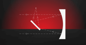
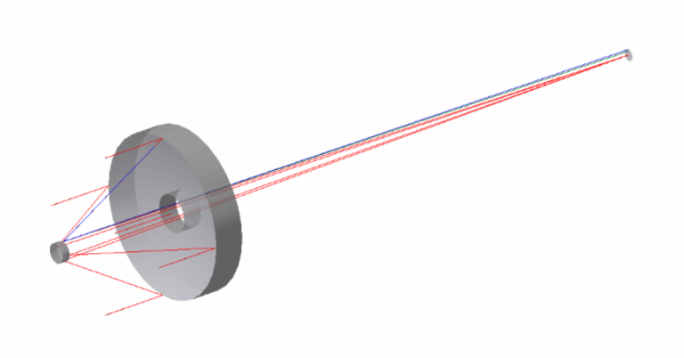
The system employs a two-mirror RC design consisting of:
- Hyperbolic primary mirror
- Hyperbolic secondary mirror
This configuration enables diffraction-limited or near-diffraction-limited performance under controlled manufacturing tolerances.
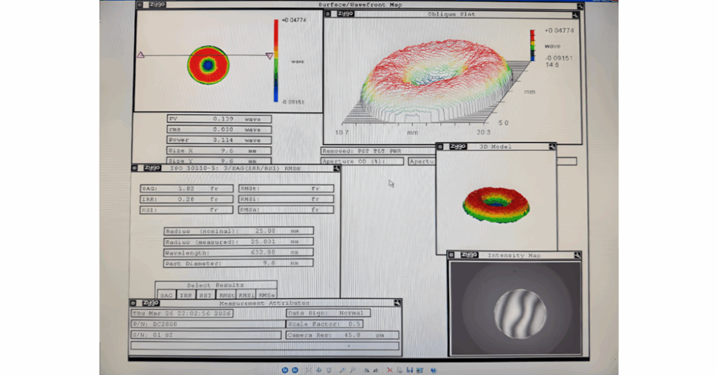
2.2 Wavefront Quality
Wavefront performance is the primary indicator of imaging quality. The system achieves:
This corresponds to high Strehl ratio performance (typically ( S > 0.8 )), indicating near-diffraction-limited imaging.
2.3 Aperture Ratio and Light Control
The aperture ratio is defined as:
Where:
- ( f ) = focal length
- ( D ) = entrance pupil diameter
At f/34, the system prioritizes:
- Suppression of stray light
- Increased depth of focus
- High-precision imaging stability
2.4 Field of View Considerations
The field of view (0.12°) is optimized for:- Narrow-field, high-resolution observation
- Targeted deep space imaging
3. Structural Design and Materials
3.1 Mechanical Architecture
The system is designed for structural stability under environmental and operational loads. Key design principles include:- Compact form factor: 293 × 290 × 274 mm
- Modular integration of optical and mechanical subsystems
- Alignment stability under thermal and mechanical variation
3.2 Material Selection
Material choices are driven by thermal stability, stiffness, and mass constraints:
Component |
Material |
Rationale |
Optical tube |
Carbon fiber |
Low CTE, high stiffness-to-weight |
Primary/secondary mirrors |
Microcrystalline glass |
Optical stability, machinability |
Backplate |
Composite material |
Structural rigidity, weight reduction |
Structural elements |
Aluminum alloy |
Manufacturability, strength |
4. Manufacturing and Assembly
4.1 Optical Fabrication
Primary and secondary mirrors are produced using:- Multi-stage precision grinding and polishing
- Surface figure control at sub-wavelength scale
- Surface roughness minimization for scattering reduction
- Surface figure accuracy
- Radius of curvature precision
- Surface roughness consistency
4.2 Structural Machining
Mechanical components are manufactured using high-precision CNC processes to ensure:- Tight dimensional tolerances
- Accurate interface alignment
- Repeatability in assembly
4.3 Alignment and Integration
System integration includes:- Optical axis alignment (coaxiality control)
- Focal plane positioning
- Iterative optical performance verification
5. System Validation and Testing
5.1 Focal Length Measurement
Focal length is determined using the rotation method:f = H tan(α)
Where:
- ( H ) = image height
- ( α ) = rotation angle
5.2 Back Focal Length (BFL)
Measured as the distance from:
- Final focal plane
- To the primary mirror vertex
Using:
- Optical interferometry
- Precision mechanical measurement tools
5.3 Wavefront Error Measurement
Wavefront error is measured via interferometry at 632.8 nm:
This cnfirms compliance with design specifications.
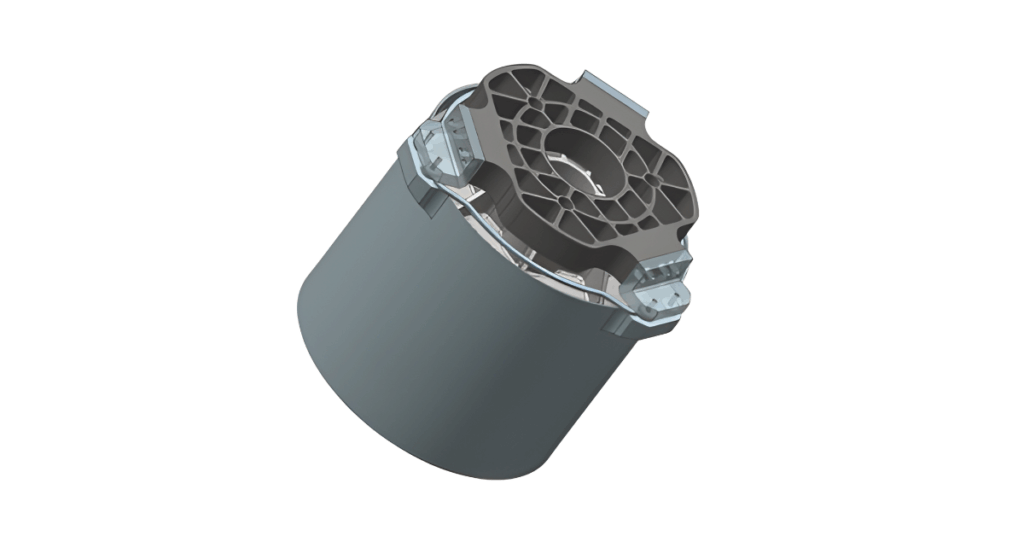
5.4 Environmental and Structural Testing
Validation includes:
- Structural stability under simulated environmental conditions
- Mass verification using precision instrumentation
- Mechanical integrity and assembly tolerance inspection
6. System Capabilities and Applications
The system is designed for high-precision optical applications including:Aerospace and Space Systems
- Optical payloads for deep space missions
- Satellite-based observation systems
- Space situational awareness (SSA)
Astronomical Observation
- High-resolution imaging of distant celestial objects
- Integration into medium-aperture observatories
Tracking and Monitoring
- Space debris tracking
- Satellite trajectory monitoring
Scientific and Institutional Use
- Advanced optical research
- Educational observatories
7. Conclusion
This RC telescope system demonstrates a fully integrated approach to high-performance optical engineering, combining:- Precision optical design
- Stable mechanical architecture
- Controlled manufacturing processes
- Verified system-level performance
GREAT ARTICLE!
Share this article to gain insights from your connections!


