Key Takeaways

  • Introduction to the impact of atmospheric attenuation on infrared radiation, emphasizing the importance of Anti-reflective Coating and Bandpass filters tailored to specific wavelengths.
  • Overview of the three main aspects of laser coatings: spectral characteristics, resistance to laser-induced damage, and wavefront distortion control.
  • Detailed specifications and applications of specific laser coatings, such as Anti-reflective Coatings for different wavelengths and Bandpass filters for targeted spectral ranges.
  • Introduction to fiber optic end caps, highlighting their cleanliness standards and capacity to withstand high laser power.

Introduction 

When infrared radiation propagates through the Earth’s atmosphere, it is influenced by various substances within the atmosphere, resulting in a decrease in the ability of light to penetrate. This phenomenon is known as atmospheric attenuation or atmospheric extinction. The impact of atmospheric extinction on infrared radiation is wavelength-dependent, showing distinct selectivity across different wavelengths. There are three wavelength intervals within the infrared spectrum that exhibit high transmittance through the atmosphere, commonly referred to as “atmospheric windows”(Figure 1). These intervals are: the near-infrared range of 1 to 3 μm, the mid-infrared range of 3 to 5 μm, and the far-infrared range of 8 to 14 μm. As a result, the target wavelengths for infrared thin films typically fall within these three wavelength ranges.Infrared imaging in different spectral bands exhibits variations in imaging mechanisms. Long-wave and mid-wave infrared imaging primarily relies on the thermal radiation emitted by objects at room temperature. On the other hand, short-wave infrared imaging predominantly utilizes the short-wave infrared radiation that is commonly present in the environment and is reflected by objects at room temperature. These distinctions determine the spectral characteristics of thin films across different wavelength ranges.

infrared, Anti-reflective Coating, wavelength, Bandpass filter
Figure 1:Atmospheric Windows

Figure/Coating

Application

Description

Material

Specification

Figure 2 – 3.7-4.8μm Anti-reflective coating

Common operating spectral range for cryogenic-ally cooled infrared detectors

InAs ,InSb ,PbS ,PbSe infrared detector response wavelength range

Ge, mono crystalline silicon , ZnS, etc

Φ25 .4×1mm

Tave>99%@3.7-4.8 μm

Figure 3 – 8-12μm Anti-reflective coating

Common operating spectral range for cryogenically No-cooled infrared detectors

Night Vision Devices, Infrared Rangefinders, Identification Equipment

Germanium, mono crystalline silicon, and chalcogenide glass, etc

Tave>98%@8- 12 μm

Figure 4 – 4.26um Bandpass filter

Applied to CO2 gas detection

High transmittance in the 4.26μm wavelength range and low transmittance in the 1.5-14μm wavelength range is required

Sapphire, mono crystalline silicon, etc.; Φ100×1mm

T>85%@4.26 μm, T<1%@1.5- 14 μm

FWHM 210nm

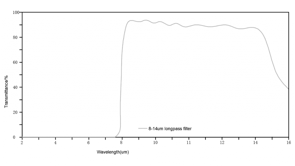
Figure 5 – 8-14μm Filter

Applied in motion detection, intrusion sensors, and human imaging detection

Germanium, monocrystalline silicon, etc.; Φ150×0.5mm

Tave >80%@8- 14 μm, T<1%@1.5-7 μm

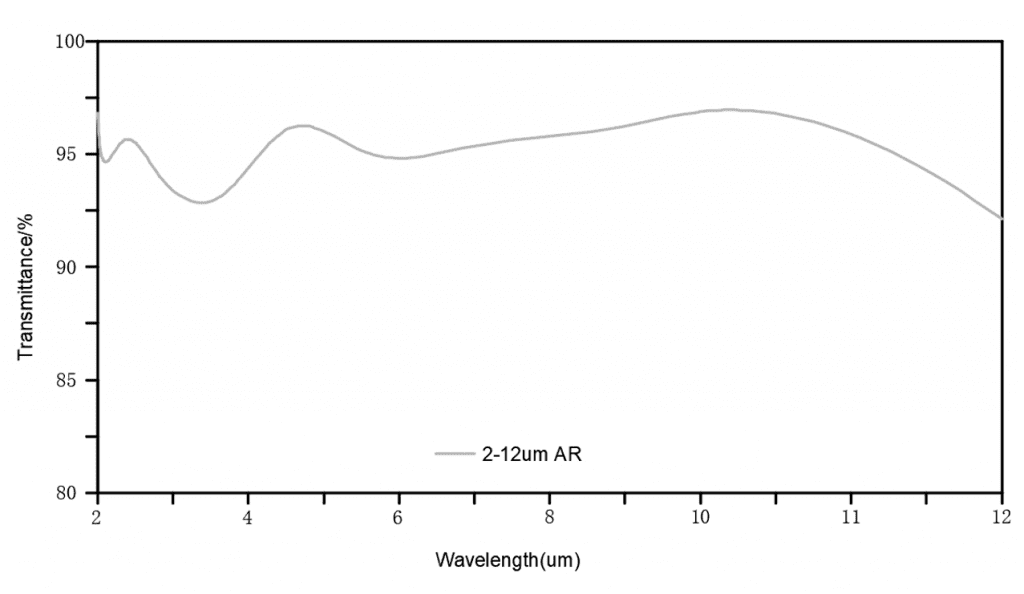
Figure 6 – 2-12 μm Filter

Detector fabricated from HgCdTe (Mercury Cadmium Telluride) material

It covers a sensitive wavelength range of 2 to 12 micrometers (μm)

Germanium, monocrystalline silicon, etc.; Φ150×0.5mm

Tave >93%@2- 12 μm

Figure 7 – 8-9.4 μm Bandpass filter

Applied for specific component detection

Germanium, monocrystalline silicon, etc.; Φ100×1mm

Tave >80%@8-9.4 μm, T<1%@5- 12 μm

 
Anti-reflective Coating, wavelength
Figure 2:3.7-4.8μm Anti-reflective coating
infrared, Anti-reflective Coating, wavelength, Bandpass filter
Figure 3:8-12μm Anti-reflective coating
Bandpass filter, wavelength
Figure 4:4.26μm Bandpass filter
filter, wavelength
Figure 5:8-14μm Filter
filter, wavelength
Figure 6:2-12μm Filter
Anti-reflective Coating
Figure 7:8-9.4μm Filter

Laser Coating Introduction

The thin films used in high-power laser systems exhibit their performance in three main aspects. Firstly, the films possess excellent spectral characteristics. Secondly, the lenses exhibit remarkable resistance to laser-induced damage. Thirdly, there is a requirement for effective control of wavefront distortion before and after coating the lenses.

For high-damage-threshold thin films, our company employs metallic hafnium as the coating material. In view of the unique properties of hafnium films, we have independently developed thin film spectral optimization algorithms and stress calculation tools. The resultant products effectively fulfill the aforementioned three conditions.

1. Anti-reflective Coating

Anti-reflective Coating, infrared

248nm Anti-reflective Coating

Applied to KrF Excimer Laser

Materials

Quartz; Φ25.4mm×2mm

Spectrum

R<0.1%@248nm

Minimal reflection, absorption, and scattering losses are required, while also aiming for a high threshold.

Transmitted Wavefront

PV<λ/10 (λ=633nm)

Damage Threshold

>1.2J/cm2@248nm, 1ns

Anti-reflective Coating, infrared

1064nmAnti-reflective Coating

Nd:YAG laser systems

Materials

JGS1, Φ25.4mm×2mm

Spectrum

T>99.9%@1064nm

Used for protecting cutting or welding heads. In order to avoid temperature rise and enhance the threshold, quartz is often employed as the substrate

Transmitted Wavefront

PV<λ/10  (λ=633nm)

Damage Threshold

>30J/cm2@1064nm, 3ns

2. High-Reflective Coating

High-Reflective Coating,infrared

Three-Band Reflective Mirror

Nd: YAG laser systems

Materials

K9; Φ50.8mm×8mm

Spectrum

R > 99.85% @351nm,
R > 99.90% @527nm,
R > 99.90% @1053nm

High reflectance for fundamental, second harmonic, and third harmonic light.

Transmitted Wavefront

PV<λ/10 (λ=632.8nm)

Damage Threshold

> 11J/cm2 @351nm, 3ns, > 27J/cm2 @527nm, 3ns,
> 59J/cm2 @1053nm 3ns

Fourth Harmonic 266nm Reflective Mirror

The 266nm wavelength is the fourth harmonic of the 1064nm laser. Unlike high-reflective coatings at 1064nm, in the 266nm wavelength range, most high-index materials (usually oxide materials) exhibit noticeable absorption. Therefore, the introduction of any impurities would degrade the spectral characteristics and damage threshold of the thin film. Additionally, due to scattering and the inverse fourth power relationship with wavelength, scattering limits the maximum achievable reflectance

Materials

JGS1; Φ25.4mm×3mm

Spectrum

R>99.6%@266nm

Reflection surface accuracy

PV<λ/10 (λ=632.8nm)

Damage Threshold

>1.5J/cm2@266nm, 3ns

3. Shortwave Pass Filter

Shortwave Pass Filter,infrared
infrared

Shortwave Pass Filter

Based on half-wave hole suppression technology and higher harmonic suppression technology, various shortwave pass filters can be fabricated

Materials

K9; Φ50.8mm×8mm

Spectrum

Tmin>80%, Tave > 95% @335nm-700nm

Rave > 99%, Rmin > 97% @720nm- 1750nm

T > 98% @527nm; R > 99.5% @1053nm

Coating

Metallic Hafnium (Hf), Electron Beam Evaporation

4. Polarizer

Thin-film polarizers are created by depositing a dielectric interference coating on the surface of a flat substrate. At a certain angle of incidence (often the Brewster angle), this design separates s-polarized light and p-polarized light, typically reflecting s-polarized light while allowing p-polarized light to transmit. A key parameter for assessing polarizer performance is extinction ratio, which is the ratio of p-polarized light transmittance to s-polarized light transmittance.

These polarizers are commonly used as alternatives to Glan-Taylor prisms and polarizing beam splitters (polarizing cubes). They offer advantages such as a large aperture, low loss, and flexible system design.

It’s important to note that due to the cone angle effect in most spectrometers and differences in the spectral characteristics of polarizing elements during inclined testing, different instruments might yield significantly varied polarized spectra. Our company has improved measurement methods and equipment, resulting in notable enhancements in the accuracy of polarizer and wide-angle spectral measurements

Materials

≥6.0

Spectrum

56°, Tp > 98%, Rs > 99.7% @1064nm

Surface accuracy

Transmission PV < λ/10, Reflection PV< λ/8 (λ=632.8nm)

Damage Threshold

P-Polarization Transmission > 35J/cm2,
S-Polarization Reflection > 18J/cm2 @1064nm, 3ns

5. Non-Polarizer

When light is incident at an inclined angle, the film layers unavoidably introduce a polarization effect. For most practical applications, this phenomenon leads to a degradation in system performance that must be eliminated or minimized. Depolarization of optical thin films is a challenging problem in thin film design. For the most commonly used long-pass and short-pass filters, our company has developed a versatile design approach to address this issue (Figure 8 and Figure 9) .

Figure 8 : Collimating Mirror Rp, s > 99.5% @1030nm-1100nm, Tp, s > 99% @960nm-985nm
wavelength, Bandpass filter, infrared, Anti-reflective Coating,
Figure 9 : Partial Reflecting Mirror Tp=Ts =50±2% @750nm-850nm

6. Bandpass Filter

A Bandpass Filter is the type of filter allows light signals to pass through within a specific wavelength range while blocking light signals outside this range on both sides. The passband of a narrowband filter is relatively narrow, typically less than 5% of the center wavelength value. The manufacturing process for these filters is usually more complex and often involves optical thickness control for process management. Therefore, when the center wavelength is shorter, the preparation method becomes particularly crucial.

wavelength, Bandpass filter, infrared, Anti-reflective Coating,

365nm Bandpass Filter

365nm is one of the emission wavelengths of mercury lamps. It is widely used in various fields such as photolithography, UV curing, metal crack detection, photocatalytic light sources, currency authentication, banknote counting devices, anti-counterfeiting industries, medical measurements

Materials

JGS1, Φ25.4mm×3mm

Spectrum

T>93%@365nm T>93%@365±1nm

wavelength, Bandpass filter, infrared, Anti-reflective Coating,

222nm Bandpass Filter

The wavelength of 222nm ultraviolet light cannot penetrate the human skin’s outermost layer, the stratum corneum, making it harmless to the human body. It also exhibits comparable germicidal effects to traditional ultraviolet lamps and has a high sterilization rate against the novel coronavirus. Common coating materials in this wavelength range do exhibit some level of absorption, which sets a certain threshold for the preparation of spectra

Materials

JGS1, Φ25.4mm×1mm

Spectrum

T>70%@222nm T<1%@245-265nm

7. Fiber optic end caps

Fiber optic end caps are a flagship product of the company. Inspection under a 40x microscope reveals no defects or blemishes, with a cleanliness level surpassing the U.S. military standard of 10-5. They can withstand laser power of up to 15,000 watts. The image below shows the typical shape and exterior appearance of an end cap(Figure 10).

Fiber optic end caps, infrared, Anti-reflective Coating,
Figure 10. Fiber optic caps

Please contact us if you’d like to schedule a consultation or request for quote on your next project. 

Related Content

GREAT ARTICLE!

Share this article to gain insights from your connections!