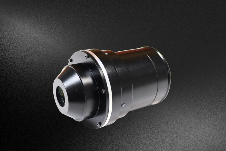
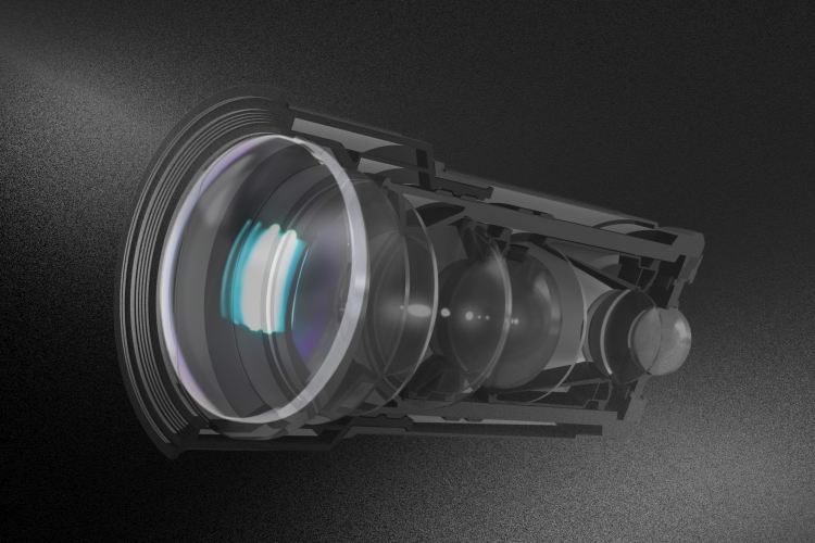
Optical Design for Manufacturing optimizes your optical components and assemblies for efficient production.
Light manipulation in laser systems demands precision micro prisms for optimal performance in any optical system.
Microlens arrays with microlenses are essential for optimizing light distribution in laser and fiber applications.
Key Takeaways Reverse Optical Engineering is pivotal for recreating or enhancing optical components, especially when original designs are unavailable or are in need of improvement. This case study showcases the necessary steps in lens reverse engineering, from customer collaboration and sample testing to optical path simulation and final lens assembly. Using advanced tools and iterative optimization, tailored solutions meet precise specifications, ensuring customer satisfaction and industry innovation. The value of reverse engineering extends to revitalizing legacy products and staying abreast of evolving optical industry demands, highlighting its crucial role in technological advancement and customer-centric design. Case Study: Lens Reverse Engineering Introduction Reverse optical engineering, including lens reverse engineering, entails comprehending the functionality of existing optical components or systems through examination. This facilitates the replication or enhancement of these components. It proves advantageous when the original design is inaccessible or when there’s a desire to enhance existing technology. This method is invaluable for crafting customized optical systems for specific needs, discerning original engineering endeavors, or replicating intricate designs efficiently and cost-effectively. This approach empowers individuals to refine the focal point of an optical system and capture detailed object information for subsequent analysis and manufacturing using the refined design. The traditional design workflow is typically “from scratch”. In reverse engineering, you start with an off-the-shelf machine or component and work backwards to disassemble each component or layer. Due to various reasons, the original manufacturer of this lens has stopped production, but there is still a small amount of demand in the market to continue the production of the lens in reverse. Specification Diameter 32mm Focal length 25mm(magnification 10X) Eye relief 25-250mm Lens reverse engineering process Customer needs to provide a sample lens First of all, the customer needs to provide two sample lenses, one for lens image quality testing, and the other for destructive testing of the parameters of the lens and structural components. At the same time, it is also necessary for the customer to provide the use scenario of the lens, so as to pay attention to the customer’s application in the later design. Figure 1 is a customer sample lens. Figure 1. Customer’s sample lens Design optical path simulation The customer needed an eyepiece with a lens that could achieve a balance between 25-200mm eye relief distance and imaging using a smartphone, and the customer had to be able to look away from the optics and maintain a good image. Key parameters are as follows: Figure 2. Customer Sample Diagram Figure 3. Optical Schematic Diagram Figure 2 and Figure 3 simulate the visual usage of two different lens Settings in existing products. Figure 2 lens does not work for long visual distance, but works well for short visual distance and has high lens resolution. Figure 3 applies to short and long visual distances, but with reduced edge resolution, the distortion is greater when using a smartphone. Retinal image Test the overall parameters of the lens Initially, the primary parameters of the lens undergo testing, encompassing focal length, entrance pupil diameter, back intercept, and image quality. Simultaneously, the lens dimensions are examined, with no alterations made to them during subsequent reverse engineering processes. Disassemble a lens and input the test lens data into the optical design software, such as Zemax. It is necessary to input the test data into the optical design software. If there is any error, the parameters need to be optimized. Spec Radius Thickness Material Diameter Doublet 50.308 10.488 H-ZK6 32 -22.723 1.477 H-ZF52A 32 -55.444 0.26 32 Singlet 33.006 6.148 H-LAK7A 32 Infinity 32 MTF (modulation transfer function) Test Result Lens overall test results Shorten the lens focal length to 25mm according to customer requirements, and optimize the lens image quality to meet customer requirements. The test results of the newly processed lens are as follows. Assembly and take pictures The actual shot picture is as follows. Lens structure Lens Reverse Engineering Conclusion The process of lens reverse engineering outlined in this case study demonstrates the meticulous steps involved in recreating optical components to meet specific requirements. By combining customer samples, rigorous testing, and advanced design software, we can craft unique solutions even without the original blueprint. Throughout the journey, collaboration with the customer remains paramount. Their input and feedback guide the design process, ensuring that the final product aligns with their needs and expectations. Additionally, iterative testing and optimization guarantee that the lens meets the desired specifications, such as focal length, image quality, and eye relief distance. Ultimately, this case study exemplifies the value of reverse engineering in revitalizing discontinued products or enhancing existing technology. By leveraging reverse engineering techniques, manufacturers can breathe new life into legacy products and consistently address evolving customer demands in the optical industry. Please contact us if you’d like to request a quote on your next project. Related Content
The reverse optical engineering process includes understanding the lens’s use, disassembly, data recording, and deriving new designs.
Laser optics in skincare are vital for tattoo removal and skin rejuvenation, targeting chromophores with precise wavelengths and pulses.
Infinite Conjugate Long Working Distance Microscope Objectives offer high magnification and more flexibility than finite conjugate systems.
Key Takeaways: Reflective microscope objectives are revolutionary in optical design, addressing challenges such as chromatic aberration and enabling diffraction-limited performance across a wide wavelength range. Their mirror-based construction reduces chromatic aberration and extends working distances, while maintaining stability and precision through uniform thermal coefficients. The two-mirror Schwarzschild objective exemplifies meticulous alignment for optimal performance. These objectives cover a broad wavelength spectrum, from deep-ultraviolet to far-infrared, proving vital in scientific, industrial, and astronomical applications. With spot sizes as small as 1 µm, they excel in high-resolution imaging tasks across fields such as biomedicine, nanotechnology, and optics research. Advancements in Reflective Microscope Objectives In the realm of optical instrument design, reflective microscope objectives represent a groundbreaking approach, conquering chromatic aberration and achieving diffraction-limited performance across a vast wavelength range. Unlike their refractive counterparts, reflective objectives rely on meticulously crafted mirror constructions to manipulate light. This leads to notable advantages such as reduced chromatic aberration and extended working distances. Focal Length and Stability The design of reflective objectives intricately links their focal length with considerations for the refractive index of the materials used. Utilizing a single material with a uniform thermal coefficient of expansion ensures these objectives maintain stability under varying environmental conditions, guaranteeing consistent performance over time. The precision engineering of corrected reflective objectives, featuring nickel spherical mirrors coated with aluminum and magnesium fluoride, exemplifies this meticulous approach. Wavelength Range The wavelength range covered by reflective objectives spans from deep-ultraviolet to far-infrared. It showcases their versatility in capturing images across different spectral regions. This broad range is especially valuable in scientific and industrial applications where precise imaging is crucial. Design Principle In terms of design, the two-mirror Schwarzschild objective is a notable example, featuring meticulous alignment of its primary mirror and secondary mirrors to achieve optimal performance. The reflective objective’s construction, including the integration of a spider assembly for the secondary mirror, plays a critical role in maintaining diffraction-limited performance and minimizing aberrations. High Resolution and Precision The spot sizes achieved with reflective objectives, such as 2 µm for the 15X objective and 1 µm for the 36X objective. They underscore their ability to produce detailed and high-resolution images. These objectives excel in tasks requiring fine detail and precision, making them indispensable tools in microscopy and related fields Applications Reflective microscope objectives find applications across a wide range of fields due to their unique design and capabilities, including diffraction-limited performance, chromatic correction, and suitability for various imaging and focusing tasks. Here are some examples of their applications: Astronomy: Achieves diffraction-limited performance and chromatic correction for precise celestial imaging. Biomedical Imaging: Essential for focused and chromatically corrected imaging of cellular structures. Nanotechnology: Analyzes nanostructures with high detail using reflective objective design. Industrial Inspection: Ensures accurate imaging for quality control and inspection tasks. Semiconductor Metrology: Utilizes reflective objectives for focused measurement and imaging. Fluorescence Microscopy: Captures accurate fluorescence signals in life sciences research. Optics Research: Versatile for precise imaging and focusing applications in various setups. The diverse applications of reflective microscope objectives underscore their importance in scientific research, and industrial and technological advancements across various disciplines. They have the ability to provide diffraction-limited performance, chromatic correction, and flexibility in imaging and focusing tasks. It makes them indispensable tools in modern microscopy and optical systems. Conclusion Reflective objectives represent a significant advancement in optical technology, offering enhanced performance in resolution, chromatic correction, and working distances. Their unique design principles contribute to diffraction-limited performance.This makes them indispensable components in modern microscope systems. Related Content
Freeform optics design enhances FOV and functionality compared to traditional optics, but requires advanced manufacturing techniques.
Key Takeaways SWIR Camera Surveillance uses SWIR light to achieve superior SWIR imaging in conditions where visible light fails. SWIR light penetrates fog and smoke better than visible light, providing clearer images. SWIR imaging is unaffected by heat haze and atmospheric variations, ensuring consistent quality. SWIR cameras use sensors like InGaAs or MCT, often integrating with existing systems with minimal changes. SWIR Camera Surveillance: Eliminating Haze There’s a deep fog over everything, and you can’t see your hand when you hold it in front of you. The perfect night for a thief to sneak into your factories, make out with whatever they can carry, and get out the same way they came— or is it? Not if you have SWIR camera surveillance. While visible light cannot penetrate well in water vapor, SWIR light has no problem that way. A SWIR camera can produce clear, high resolution images even when the human eye is unable to make heads or tails of anything. Here we’ll look at just what SWIR can do and how it does it. SWIR camera surveillance makes it possible to get a clear view of a foggy landscape. The Foundations of SWIR Camera Surveillance SWIR is short for short wave infrared and is the part of the spectrum with wavelength between 0.9 and 1.7 microns. Photons of SWIR light are absorbed and reflected from an object in a way analogous to visible light. It enables a high dynamic range and good contrast in imaging. But this light is invisible to the human eye, and the silicon sensors used for visible light imaging don’t work with SWIR. Dedicated SWIR sensors (typically made of InGaAs or MCT) are used instead. SWIR lighting can illuminate an industrial complex at night while maintaining the appearance of darkness. Outdoors, natural SWIR (‘night glow’) is present under nearly all weather conditions, both day and night. Night glow is a type of atmospheric radiance that allows SWIR camera surveillance in even the darkest nights. Why SWIR Camera Surveillance? We’ve touched briefly on why short wave infrared SWIR camera surveillance is so important to a wide range of applications, but let’s look at it in more detail now. The importance of SWIR imaging lies in its wavelength. Since SWIR light has a shorter wavelength than visible light, it isn’t scattered by the microparticles of fog and smoke. This makes SWIR imaging more effective in such conditions compared to visible light. Heat haze and atmospheric temperature variances can cause havoc with thermal imaging. However, these factors do not affect SWIR imaging. This makes SWIR imaging ideal for ensuring clear images at any time, whether it is night or morning. It also works effectively regardless of the atmospheric conditions. Visible LWIR SWIR SWIR camera surveillance can provide clear images even when both visible and LWIR imaging fails. Is that the only reason major players in industry, defense, and security are turning to SWIR camera surveillance? No, there are more. One benefit of SWIR vision systems is that no visible illumination is needed. As mentioned in the last section, a powerful beam of SWIR light can illuminate a setting that looks dark to everyone using more traditional imaging equipment. A SWIR sensor can also be used to locate lasers and beacons, making it helpful in keeping track of mobile teams or for military IR laser spotting and tracking. In biometrics, SWIR can be used to distinguish between fake hair and human hair. This enables easy identification of individuals who might be attempting to disguise their identity. Human hair will appear light, while fake hair shows up as dark. There’s nothing easier than picking out a person who is carrying around a head of hair that was manufactured in a factory. SWIR Imaging Equipment The InGaAs sensors used for SWIR imaging are manufactured from indium gallium arsenide. These sensors can detect light radiation ranging from 550nm to as high as 2.5μm. An alternative to InGaAs is MCT, or mercury-cadmium detector, which can detect into the long wave infrared LWIR region. The benefit of MCT is that it is ‘tunable’. The optical absorption wavelength changes based on the cadmium concentration. This allows the amount of cadmium (Cd) to be chosen to create a sensor that absorbs optimally in a given region. There is a big downside to MCT sensors, however— they must be cryogenically cooled. SWIR radiation travels through glass in much the same way as visible light. This means that standard camera lenses, mirrors, and other optics can be used in short wave cameras. If you’d like to switch your existing surveillance system over to SWIR you may need to make only small modifications. It may take less than you think to set up your new SWIR camera surveillance system. Custom SWIR Camera Surveillance At Avantier, we’re all about producing custom optics that enable our customers to reach their performance goals, no matter what the application. Whether you need a SWIR camera with high frame rates and low exposure time, a SWIR vision system for an unmanned vehicle, or SWIR imaging equipment for a research project, we can assist you. We provide the optical components and lens assemblies necessary for your specific needs. Just let us know your requirements, and we’ll tailor our solutions accordingly. Related Content