
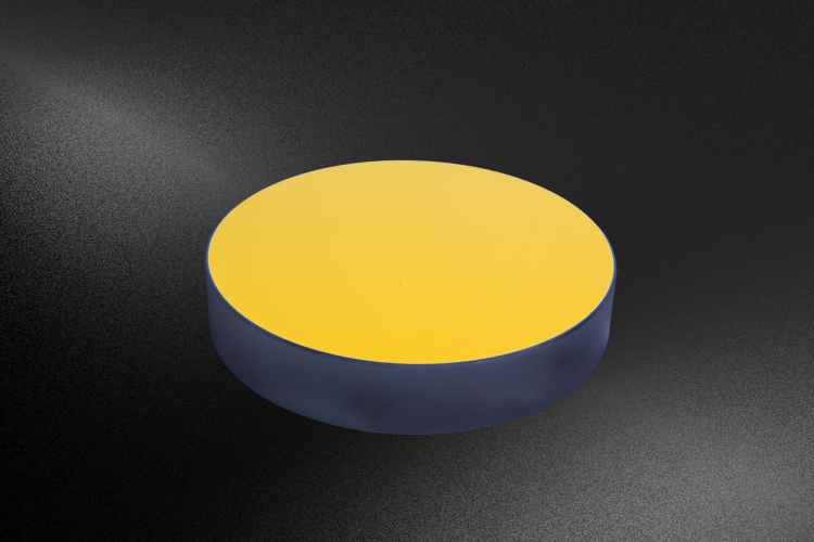
Supporting future mission like LUVIOR and HabEx, Avantier’s successful development of the Φ1.1 m RB-SiC mirror will foster new discoveries, offering clearer views of our universe with unprecedented efficiency and precision.

Supporting future mission like LUVIOR and HabEx, Avantier’s successful development of the Φ1.1 m RB-SiC mirror will foster new discoveries, offering clearer views of our universe with unprecedented efficiency and precision.
Optical coatings manipulate the fundamental properties of light—reflection, transmission, polarization, and spectral distribution—through thin-film engineering that enhances performance in advanced optical systems.

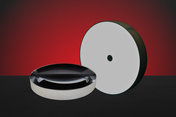
This project required the development of a germanium lens designed for use in low-visibility environments such as fog, smoke, or low-light. Learn how Avantier successfully exceeded expectations, demonstrating capabilities to manufacture specialized lenses for demanding applications.
Cylindrical lenses focus incident light onto a focal line, playing an indispensable role in laser beam shaping, linear array scanning, spectral analysis, and optical fiber communications.
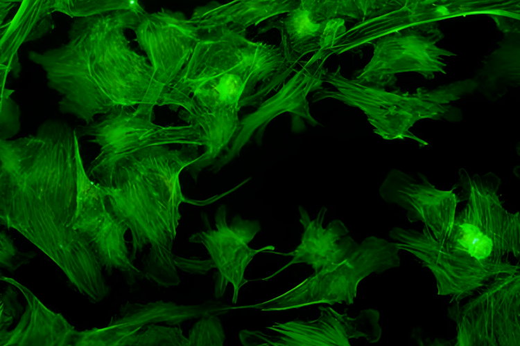
Fluorescence microscopy has emerged as a pivotal tool for observing cellular structures, tracking molecular dynamics, and deciphering the mechanisms of life, offering high specificity through fluorescent labeling and enabling sensitive visualization of biological processes that are otherwise invisible under conventional imaging techniques.
As optical systems continue to demand higher resolution, greater sensitivity, and improved measurement accuracy, aperture size remains a central performance driver of imaging and measurement performance.
Precision Telecompressors redefine imaging efficiency, pairing full-frame optics with smaller sensors while preserving field of view, sharpening detail, and strengthening low-light performance across advanced applications.
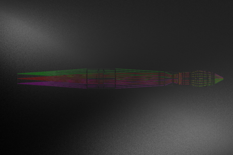
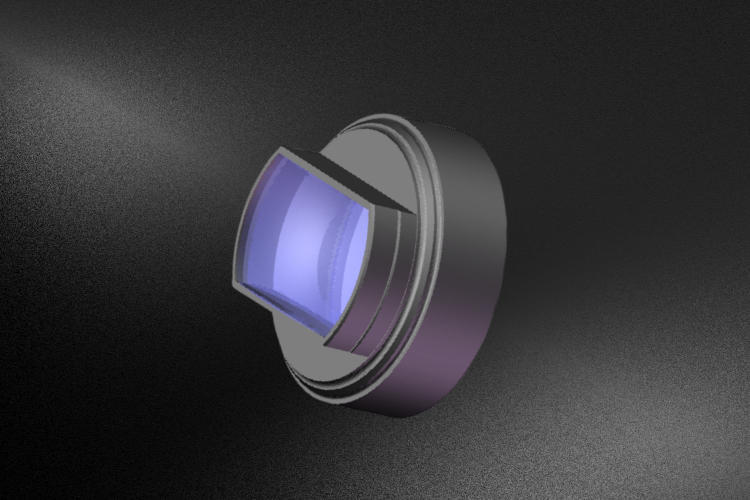
Key Takeaways The Infinite Conjugate Microscope Objective delivers superior optical flexibility, enabling modular imaging paths through its collimated beam design. High numerical aperture, advanced aberration correction, and optimized working distances provide exceptional resolution and measurement accuracy. Its robust optical and mechanical engineering supports multimodal imaging, UV–IR operation, and integration with laser systems. These capabilities make […]

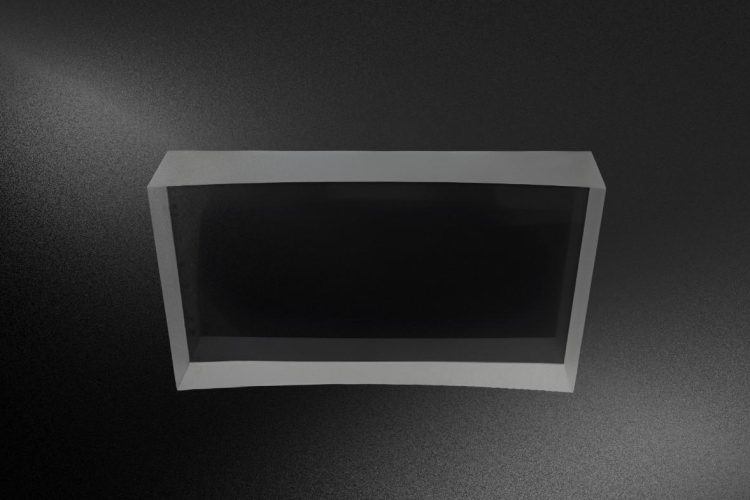
This project required designing a lightweight NIR reflection mirror with a machined backside pocket structure; Avantier considered manufacturability, structural integrity, thermal behavior and operational reliability in providing a stable, production-ready solution.
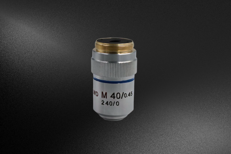
Finite conjugate microscope objectives remain an efficient solution to achieving high-resolution imaging in applications requiring compactness, stability, and cost-effective excellence, making them indispensable in industrial inspection, portable diagnostics, and micro-nano machining.