

Key Takeaways
- Reverse engineering an optical system is not simply a matter of copying measured geometry.
- A physical sample reflects manufacturing tolerances, assembly errors, wear, and aging—not only original design intent.
- Reliable reconstruction requires correlating component measurements with system-level optical performance.
- Modern materials, coatings, and mechanical architectures can improve manufacturability and performance without unnecessarily changing the recovered optical design.
- The final goal is not an identical artifact, but a verified, manufacturable optical system that reproduces the required function.
When an optical component becomes obsolete, reproducing it may appear as a measurement problem: measure the radii, thicknesses, materials, and mechanical dimensions, then manufacture the same part.
In practice, a physical lens is not the original design. It is one manufactured instance of that design, affected by fabrication tolerances, assembly error, wear, coating degradation, and years of operation.
Avantier recently faced this problem with a discontinued projection microscope objective used in an older inspection system. The original manufacturer no longer supplied the component, no suitable replacement was available, and the only practical starting point was the physical lens itself.
The challenge was therefore not simply to copy the sample, but to infer the design intent behind the measured lens and rebuild it in a form that could be manufactured reliably today.
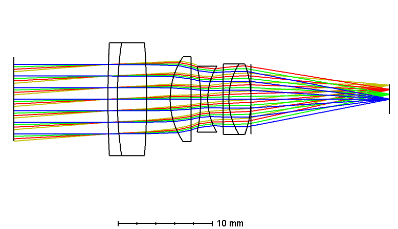
- Number of Individual Lenses: 2
- Number of Cemented Lens Groups: 2
- Threaded Interface: M18.5 × 0.5
- Approximate Overall Dimensions: Ø18 mm × 21.6 mm (L)
Reconstructing the Optical Prescription
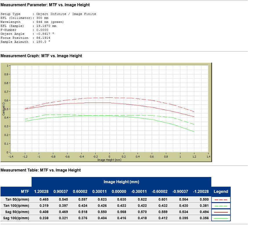
Before disassembly, we characterized the objective as a complete optical system; measurements such as MTF, wavefront aberration, focal length, chromatic behavior, and distortion provide a baseline against which the reconstructed model can later be evaluated.
This matters because geometric agreement alone does not prove that the design has been reconstructed correctly.
After system characterization, the objective was disassembled and measured at component level. Optical measurements included curvature and physical dimensions, while mechanical components were mapped separately. Optical material properties also had to be characterized.
The first optical model can be built from these measurements—but it should not automatically be treated as the nominal prescription.
A used sample may contain manufacturing variation, spacing errors, decenter, thread wear, coating degradation, or deformation accumulated over its service life. The measured geometry is therefore better treated as an initial hypothesis.
The reconstruction becomes an iterative process:
measurement → optical model → simulated performance → comparison with measured system performance → adjustment
The objective is to find a physically plausible prescription that is consistent with both the measured components and the observed optical performance of the complete system.
Material Reconstruction
Geometry alone is not enough. Optical glass is part of the prescription. Refractive index and Abbe number, together with material analysis, can be measured and used to identify or approximate the original glass. If the original material is obsolete or impractical to source, available substitutes must then be evaluated in the complete optical model. The key question is not simply which glass has the closest catalog values, but which available material allows the system to recover the required optical performance after re-optimization.What We Changed Instead of Simply Copying
Once the prescription had been reconstructed, we did not assume that every historical manufacturing choice should be reproduced unchanged. Two areas offered practical opportunities for improvement: the optical coating and the mechanical architecture.Updating the Coating
Using current coating processes, we redesigned the coating without changing the substrate optical prescription. The revised coating is expected to achieve a single-surface transmittance of ≥99% at 450 nm and an average single-surface transmittance of ≥98% over 400–700 nm. Based on these values, the total transmittance of the complete objective is expected to improve by approximately 2–3 percentage points, from about 96% to approximately 98–99% on average. The revised coating achieved:- ≥99% transmittance at 450 nm
- ≥98% average transmittance over 400–700 nm
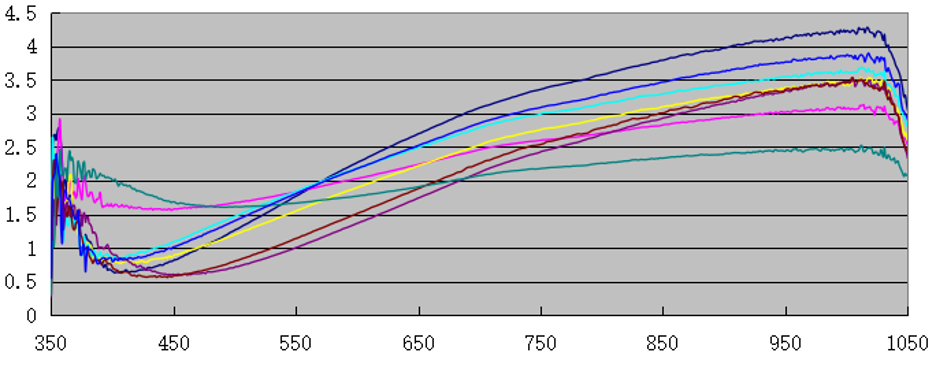
The objective consists of four lens groups—two cemented doublets and two singlet lenses—resulting in eight optical surfaces exposed to air. Each curve represents the measured spectral reflectance of one individual air-contacting surface. Reflectance is minimized around 450 nm, indicating that reflection losses are lowest in this wavelength region.
Rethinking the Mechanical Architecture
The original objective used a four-section threaded structure. Its main advantage was serviceability: individual optical groups could be removed independently. For a precision inspection application, however, multiple threaded interfaces also create accumulated alignment risk. Thread wear and assembly variation can affect coaxiality between optical groups, turning a mechanical tolerance problem into an optical performance problem. After reviewing the customer’s actual operating and maintenance requirements, the replacement was changed to an integrated retaining-ring-based barrel configuration. The decision was a trade-off:Original threaded structure
- Easier replacement of individual optical groups
- More mechanical interfaces
- Greater sensitivity to accumulated assembly variation
- Reduced serviceability at individual-group level
- Better suited to repeatable optical-axis control
- More appropriate where imaging consistency is the priority
Designing the Reconstructed Lens for Production
Recovering a nominal optical design is only part of the job. The design must also tolerate real manufacturing variation.
We therefore evaluated the effects of curvature, center thickness, element decenter, spacing, and assembly variation through tolerance analysis and Monte Carlo simulation.
The purpose was not to make every tolerance as tight as possible. Excessively tight tolerances increase manufacturing cost and may make the design impractical, while overly loose tolerances reduce yield and unit-to-unit consistency.
The engineering task is to identify which parameters actually dominate system performance and define a production window around them.
This is the point where reverse engineering becomes more than reconstruction of a successful prototype. It becomes a repeatable manufacturing process.
Verification: Closing the Loop
The final test is not whether the replacement reproduces every measured dimension of the original sample.
It is whether it reproduces the required optical function.
The complete validation loop is:
original sample → measured baseline → reconstructed model → manufactured replacement → measured verification
For an inspection objective, the most relevant comparisons may include MTF across the field, distortion, chromatic performance, working distance, transmission, and unit-to-unit consistency.
A successful reconstruction should therefore be judged against application-level optical performance—not dimensional similarity alone.
Reconstructing the Design, Not the Artifact
A lens without drawings does not contain its nominal prescription in directly readable form.
Its surfaces can be measured. Its materials can be characterized. Its mechanical structure can be mapped. Its optical behavior can be tested.
But those measurements still have to be interpreted.
For this projection microscope objective, reverse engineering meant separating design intent from the condition of one physical sample and reconstructing an optical model consistent with measured performance. It also meant updating technologies where appropriate, and defining a design that could return to production.
That is the difference between copying a lens and reconstructing an optical design.
Need to Reconstruct an Optical Component Without Complete Design Data?
If a discontinued or undocumented optical component is becoming a constraint on maintenance, production, or system upgrades, we can help evaluate whether it can be reconstructed from an existing sample.
Our reverse engineering work covers optical characterization, prescription reconstruction, material identification and substitution, coating redesign, mechanical optimization, tolerance analysis, and production verification.
Talk to our engineering team about your optical reverse engineering project.






GREAT ARTICLE!
Share this article to gain insights from your connections!