
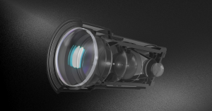
Infrared Lenses (IR Lenses)
Avantier designs and manufactures custom infrared (IR) lenses for advanced applications in
- Manufacturing
- Defense and security
- Scientific research
- Medical diagnostics
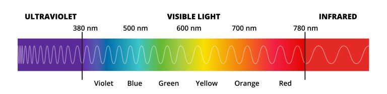
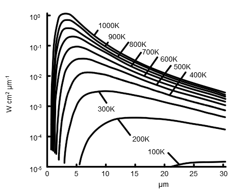
IR lenses operate beyond the visible light spectrum, capturing and focusing infrared radiation to enable high-precision thermal imaging and detection.
Key IR Lens Types
We offer optical systems across the full infrared spectrum, including:
Each lens type is optimized for its target wavelength range and application.
Factory Standard (Manufacturing Capability)
| SWIR lens | MWIR lens | LWIR lens | NIR lens | |
|---|---|---|---|---|
| Wavelength | 0.9 um-2.5 um | 3 um-5 um | 8 um-12 um | 0.9 um-1.5 um |
| Focal length | 25 mm | 50 mm | 6 mm | 25 mm |
| F/# | 2.5 | 0.94 | 1 | 2 |
| Sensor | 2/3″ | 2/3″ | 1″ | 2/3″ |
| FOV | 25° | 13° | 128° | 25° |
Custom IR Lens Options
Avantier specializes in fully customized IR lens systems, from prototyping to volume production.
- Custom Specifications: Tailored to meet your exact performance metrics, from resolution to spectral response.
- Lens Types
- Aspherical lenses
- Spherical lenses
- Cylindrical lenses
- Custom geometries and assemblies
- Precision Optical Design: Our engineers use advanced simulation software to optimize for:
- Thermal stability
- Low distortion
- Aberration correction
- High transmission efficiency
- Material Selection Guidance: Based on your target infrared band and operating environment, we select optimal substrates to ensure durability and performance.
- Custom Coatings: We offer anti-reflection (AR) coatings tailored to the target spectral range:
- Visible
- NIR
- SWIR
- MWIR
- LWIR
- Coatings improve optical transmission, minimize reflection losses, and provide environmental protection.
- Advanced Manufacturing: Using high-precision processes like diamond turning, CNC machining, and precision molding, we deliver IR optics with exceptional surface quality and dimensional accuracy.
Material Selection
- Germanium (Ge)
- Zinc Selenide (ZnSe)
- Chalcogenide glass
- Zinc Sulfide (ZnS)
- Silicon (Si)
- Sapphire (Al₂O₃)
- Calcium Fluoride (CaF₂)
- Cadmium Telluride (CdTe) – as needed for specialized applications
| Refractive index | Transmission spectrum | |
| CaF2 | 1.414@3.5 μm | 0.23-9.7 μm |
| Ge | 4.033@3.5 μm | 2-15 μm |
| Chalcogenide | 2.0~3.0@10μm | 0.6-20 μm |
| CdTe | 2.677@8.0 μm | 6-22 μm |
| Sapphire | 1.695@3.5 μm | 0.2-5.5 μm |
| Si | 3.428@3.5 μm | 1.36-11 μm |
| ZnSe | 2.417@8 μm | 0.55-18 μm |
| ZnS | 2.223@8 μm | 0.42-18 μm |
Stock IR Lenses
Near-Infrared (NIR) Lenses
| Part Number | Wavelength (μm) | EFL (mm) | F# | FOV | Sensor |
|---|---|---|---|---|---|
| AVTIR-0001 | 0.9-1.7 | 17 | 2 | 79.2˚(D) | 6000X4000,3.9μm |
| AVTIR-0002 | 0.9-1.7 | 25 | 1.4 | 44.6˚(D) | 640X480,25μm |
| AVTIR-0003 | 0.9-1.7 | 200 | 2.4 | 3.5˚(D) | 640X512,15μm |
| AVTIR-0004 | 0.9-1.7 | 12.5 | 1.4/16 | 37°(D) | 640X512,15μm |
| AVTIR-0005 | 0.9-1.7 | 17 | 2 | 79.2(D) | 6000X4000,3.9μm |
| AVTIR-0006 | 0.9-1.7 | 75 | 1.5 | 9.4°(D) | 640X512,15μm |
| AVTIR-0007 | 0.9-1.7 | 200 | 2.4 | 3.5°(D) | 640X512,15μm |
Short-Wave Infrared (SWIR) Lenses
| Part Number | Wavelength (μm) | EFL (mm) | F# | FOV | Sensor |
|---|---|---|---|---|---|
| AVTIR-0008 | 1-3 | 12 | 3 | 54˚(D) | 640X512,15μm |
| AVTIR-0009 | 1-3 | 23 | 2 | 30˚(D) | 320X256,30μm |
| AVTIR-0010 | 1-3 | 25 | 2.5 | 26˚(D) | 320X256,30μm |
| AVTIR-0011 | 1-3 | 35 | 2 | 10˚(D) | 320X256,30μm |
| AVTIR-0012 | 1-3 | 50 | 2 | 14˚(D) | 320X256,30μm |
| AVTIR-0013 | 1-3 | 50 | 2.3 | 24.5˚(D) | 1024X768,17μm |
| AVTIR-0014 | 1-3 | 200 | 2.5 | 2.7˚(H)X2.2˚(V) | 640X512,15μm |
| AVTIR-0015 | 1.5-5 | 12 | 3 | 54°(D) | 1024X768,17μm |
| AVTIR-0016 | 1-3 | 23 | 2 | 30°(D) | 320X256,30μm |
| AVTIR-0017 | 0.9-2.5 | 25 | 2.5 | 26°(D) | 320X256,30μm |
| AVTIR-0018 | 1.5-5 | 25 | 3 | 50°(D) | 1024X768,17μm |
| AVTIR-0019 | 0.9-2.5 | 35 | 2 | 10°(D) | 320X256,30μm |
| AVTIR-0020 | 0.9-2.5 | 50 | 2 | 14°(D) | 320X256,30μm |
| AVTIR-0021 | 1.5-5 | 50 | 2.3 | 24.5°(D) | 1024X768,17μm |
| AVTIR-0022 | 0.9-2.5 | 75 | 2 | 9.4°(D) | 640X512,15μm |
| AVTIR-0023 | 1.5-5 | 100 | 2.3 | 12.5°(D) | 1024X768,17μm |
| AVTIR-0024 | 1-3 | 200 | 2.5 | 3.5°(D) | 640X512,15μm |
Mid-Wave Infrared (MWIR) Lenses
| Part Number | Wavelength (μm) | EFL (mm) | F# | FOV | Sensor |
|---|---|---|---|---|---|
| AVTIR-0025 | 3-5 | 15 | 1 | 44.5˚(D) | 320X256,30μm |
| AVTIR-0026 | 3-5 | 15 | 3 | 15.5°(H)X15.5°(V) | 2750X2750,15μm |
| AVTIR-0027 | 3-5 | 25 | 2 | 27.6˚(D) | 640X512,15μm |
| AVTIR-0028 | 3-5 | 35 | 3 | 104˚(D) | 2750X2750,15μm |
| AVTIR-0029 | 3-5 | 50 | 2 | 10.9°(H)X8.7°(V) | 640X512,15μm |
| AVTIR-0030 | 3-5 | 50 | 3 | 21.7°(H)X17.4°(V) | 1280X1024,15μm |
| AVTIR-0031 | 3-5 | 50 | 3.75 | 27.6˚(D) | 1280X1024,15μm |
| AVTIR-0032 | 3-5 | 50 | 4 | 14.5˚(D) | 1024X768,10μm |
| AVTIR-0033 | 3-5 | 50 | 4 | 27.6˚(D) | 1280X1024,12μm |
| AVTIR-0034 | 3-5 | 50 | 4 | 14˚(D) | 640X512,15μm |
| AVTIR-0035 | 3-5 | 70 | 2 | 7.8°(H)X6.3°(V) | 640X512,15μm |
| AVTIR-0036 | 3-5 | 100 | 2 | 11.2˚(D) | 640X512,24μm |
| AVTIR-0037 | 3-5 | 200 | 4 | 7˚(D) | 1280X1024,12μm |
| AVTIR-0038 | 3-5 | 200 | 4 | 3.2˚(D) | 2750X2750,15μm |
| AVTIR-0039 | 3-5 | 10 | 4.5 | 69.6°(D) | 640X512,15μm |
| AVTIR-0040 | 3-5 | 15 | 1 | 44.5°(D) | 640X512,15μm |
| AVTIR-0041 | 3-5 | 15 | 3 | 21.5°(D) | 2750X2750,15μm |
| AVTIR-0042 | 3-5 | 25 | 2 | 27.6°(D) | 640X512,15μm |
| AVTIR-0043 | 3-5 | 35 | 3 | 104°(D) | 2750X2750,15μm |
| AVTIR-0044 | 3-5 | 50 | 2 | 14°(D) | 640X512,15μm |
| AVTIR-0045 | 3-5 | 50 | 3 | 27.6°(D) | 1280X1024,15μm |
| AVTIR-0046 | 3-5 | 50 | 3.75 | 27.6°(D) | 1280X1024,15μm |
| AVTIR-0047 | 3-5 | 50 | 4 | 14.5°(D) | 1024X768,10μm |
| AVTIR-0048 | 3-5 | 50 | 4 | 27.6(D) | 1280X1024,15μm |
| AVTIR-0049 | 3-5 | 50 | 4 | 14°(D) | 640X512,15μm |
| AVTIR-0050 | 3-5 | 70 | 2 | 10°(D) | 640X512,15μm |
| AVTIR-0051 | 3-5 | 100 | 2 | 11.2(D) | 640X512,24μm |
| AVTIR-0052 | 3-5 | 200 | 4 | 7(D) | 1280X1024,15,12μm |
| AVTIR-0053 | 3-5 | 200 | 4 | 3.2(D) | 2750X2750,15μm |
Motorized Mid-Wave Infrared (MWIR) Lenses
| Part Number | Wavelength (μm) | EFL (mm) | F# | FOV | Sensor |
|---|---|---|---|---|---|
| AVTIR-0054 | 3-5 | 200 | 2 | 2.7°(H)X2.2°(V) | 640X512,15μm |
| AVTIR-0055 | 3-5 | 30-300 | 4 | 18.1˚(H)-1.8˚(H) | 320X256,15μm |
| AVTIR-0056 | 3-5 | 30-300 | 4 | 18.1˚(H)-1.8˚(H) | 640X512,15μm |
| AVTIR-0057 | 3-5 | 200 | 2 | 2.7°X2.2° | 640X512,15μm |
| AVTIR-0058 | 3-5 | 30/300 | 4 | 18.1(H)/1.8°(H) | 640X512,15μm |
Long-Wave Infrared (LWIR) Wide-Angle Lenses
| Part Number | Wavelength (μm) | EFL (mm) | F# | FOV | Sensor |
|---|---|---|---|---|---|
| AVTIR-0059 | 8-12 | 4.4 | 1 | 180˚(H)X136˚(V) | 800X600,17μm |
| AVTIR-0060 | 8-12 | 4.6 | 1 | 94.5˚(H)X103.3˚(V) | 640X480,17μm |
| AVTIR-0061 | 8-12 | 5.5 | 1 | 73˚(D) | 384X288,17μm |
| AVTIR-0062 | 8-12 | 5.6 | 1 | 140˚(H)X110˚(V) | 800X600,17μm |
| AVTIR-0063 | 8-12 | 7.2 | 1 | 110˚(H)X80˚(V) | 800X600,17μm |
Motorized Long-Wave Infrared (LWIR) Lenses
| Part Number | Wavelength (μm) | EFL (mm) | F# | FOV | Sensor |
|---|---|---|---|---|---|
| AVTIR-0064 | 8-12 | 21 | 1 | 15.6˚(H)X11.9˚(V) | 336X256,17μm |
| AVTIR-0065 | 8-12 | 25 | 1 | 30.4˚(D) | 384X288,17μm |
| AVTIR-0066 | 8-12 | 30 | 1 | 20.5˚(H)X15.5˚(V) | 640X480,17μm |
| AVTIR-0067 | 8-12 | 30 | 1 | 26.2˚(D) | 640X480,17μm |
| AVTIR-0068 | 8-12 | 40 | 1 | 18.6˚(D) | 336X256,17μm |
| AVTIR-0069 | 8-12 | 40 | 1 | 18.6˚(D) | 640X480,17μm |
| AVTIR-0070 | 8-12 | 50 | 1 | 12.4˚(H)X9.3˚(V) | 640X480,17μm |
| AVTIR-0071 | 8-12 | 75 | 1 | 8.2˚(H)X6.2˚(V) | 640X480,17μm |
| AVTIR-0072 | 8-12 | 75 | 1 | 5.9˚(H)X4.7˚(V) | 640X512,12μm |
| AVTIR-0073 | 8-12 | 100 | 1 | 8.8˚(H)X7˚(V) | 1280X1024,17μm |
Long-Wave Infrared (LWIR) Continuous Zoom Lenses
| Part Number | Wavelength (μm) | EFL (mm) | F# | FOV | Sensor |
|---|---|---|---|---|---|
| AVTIR-0074 | 8-12 | 15-60 | 0.8-1.0 | 40˚(H)-10.4˚(H) | 640X512,17μm |
| AVTIR-0075 | 8-12 | 20-100 | 1.2 | 24.6˚(H)-6.2˚(H) | 640X512,17μm |
| AVTIR-0076 | 8-12 | 25-75 | 1.2 | 24.6˚(H)-8.3˚(H) | 640X512,17μm,12μm |
| AVTIR-0077 | 8-12 | 30-150 | 0.85/1.2 | 20.5˚(H)-4.1˚(H)/12.4˚(H)-2.5˚(H) | 384X288,17μm |
| AVTIR-0078 | 8-12 | 30-150 | 0.85/1.2 | 20.5˚(H)-4.1˚(H)/12.4˚(H)-2.5˚(H) | 640X480,17μm |
| AVTIR-0079 | 8-12 | 30-150 | 0.85/1.2 | 20.5˚(H)-4.1˚(H) | 640X512,17μm |
| AVTIR-0080 | 8-12 | 25-225 | 1.5 | 24.5˚(H)-2.7˚(H)/14.8˚(H)-1.6˚(H) | 384X288,17μm |
| AVTIR-0081 | 8-12 | 25-225 | 1.5 | 24.5˚(H)-2.7˚(H)/14.8˚(H)-1.6˚(H) | 640X512,17μm |
| AVTIR-0082 | 8-12 | 13/45 | 0.8-1 | 33°(H)/9.7(H) | 640X512,12μm |
| AVTIR-0083 | 8-12 | 15/60 | 0.9-1 | 62(H)/14°(H) | 1024X768,12μm |
| AVTIR-0084 | 8-12 | 25-75 | 1.2 | 25°(H)/8.3°(H) | 640X512,17μm |
| AVTIR-0085 | 8-12 | 20-100 | 1.2 | 30.2(H)/6.1(H) | 640X512,17μm |
| AVTIR-0086 | 8-12 | 30/150 | 0.85/1.2 | 20.5°(H)/4.1(H) | 640X512,17μm |
| AVTIR-0087 | 8-12 | 25/225 | 1.5 | 24.5°(H)/2.7(H) | 640X512,17μm |
Long-Wave Infrared (LWIR) Lenses
| Part Number | Wavelength (μm) | EFL (mm) | F# | FOV | Sensor |
|---|---|---|---|---|---|
| AVTIR-0088 | 8-12 | 4 | 2 | 104°(H)X91.4°(V) | 640X512,16μm |
| AVTIR-0089 | 8-12 | 7 | 1.1 | 80°(H)X60°(V)X102°(D) | 640X480,17μm |
| AVTIR-0090 | 8-12 | 7 | 2 | 72.4°(H)X60.7°(V) | 640X512,16μm |
| AVTIR-0091 | 8-12 | 7.4 | 1.1 | 53°(H)X39°(V)X68°(D) | 384X288,17μm |
| AVTIR-0092 | 8-12 | 7.5 | 1 | 84.4°(D) | 320X240,25μm |
| AVTIR-0093 | 8-12 | 7.5 | 1 | 84.4°(D) | 640X480,17μm |
| AVTIR-0094 | 8-12 | 10 | 1 | 36.2°(H)X27.5°(V)X44.4°(D) | 384X288,17μm |
| AVTIR-0095 | 8-12 | 13 | 1.2 | 33.6°(H)X27°(V)X43.4°(D) | 640X512,12μm |
| AVTIR-0096 | 8-12 | 15 | 1 | 48.8°(D) | 320X240,25μm |
| AVTIR-0097 | 8-12 | 15 | 1 | 24.5°(H)X18.4°(V)X30.6°(D) | 384X288,12μm |
| AVTIR-0098 | 8-12 | 15 | 1 | 17.3°(H)X13(V)X21.6(D) | 384X288,12μm |
| AVTIR-0099 | 8-12 | 15 | 1 | 48.8°(D) | 640X480,17μm |
| AVTIR-0100 | 8-12 | 15 | 2 | 37.7°(H)X30.6°(V) | 640X512,16μm |
| AVTIR-0101 | 8-12 | 19 | 1 | 39°(D) | 320X240,25μm |
| AVTIR-0102 | 8-12 | 19 | 1 | 12.2°(H)X10.4°(V)X17.2°(D) | 384X288,12μm |
| AVTIR-0103 | 8-12 | 19 | 1.1 | 39°(D) | 384X288,17μm |
| AVTIR-0104 | 8-12 | 19 | 1 | 22.8°(H)X17.2°(V)X28.9°(D) | 640X480,12μm |
| AVTIR-0105 | 8-12 | 19 | 1 | 39°(D) | 640X480,17μm |
| AVTIR-0106 | 8-12 | 19 | 1.1 | 39°(D) | 640X480,17μm |
| AVTIR-0107 | 8-12 | 19 | 1.1 | 32°(H)X24°(V)X39.4°(D) | 640X480,17μm |
| AVTIR-0108 | 8-12 | 20 | 2 | 27°(H)X20.4°(V)X35.2°(D) | 384X288,25μm |
| AVTIR-0109 | 8-12 | 22.6 | 1 | 16.4°(H)X12.4°(V) | 384X288,17μm |
| AVTIR-0110 | 8-12 | 25 | 1 | 69.7°(H)X55.1°(V)X82°(D) | 2048X1536,17μm |
| AVTIR-0111 | 8-12 | 25 | 1 | 9.2°(H)X7.8°(V)X13°(D) | 384X288,12μm |
| AVTIR-0112 | 8-12 | 25 | 1.1 | 30.4°(D) | 384X288,17μm |
| AVTIR-0113 | 8-12 | 25 | 1 | 30.4°(D) | 384X288,17μm |
| AVTIR-0114 | 8-12 | 25 | 1 | 30°(D) | 384X288,17μm |
| AVTIR-0115 | 8-12 | 25 | 1.1 | 10.9°(H)X8.2°(V)X13.6°(D) | 400X300,12μm |
| AVTIR-0116 | 8-12 | 25 | 1.1 | 15.4°(H)X11.6°(V)X19.2°(D) | 400X300,17μm |
| AVTIR-0117 | 8-12 | 25 | 1 | 17.4°(H)X13°(V)X21.6°(D) | 640X480,12μm |
| AVTIR-0118 | 8-12 | 25 | 1.1 | 30.4°(D) | 640X480,17μm |
| AVTIR-0119 | 8-12 | 25 | 1.1 | 24.5°(H)X18.5°(V)X30.4°(D) | 640X480,17μm |
| AVTIR-0120 | 8-12 | 25 | 1 | 30.4°(D) | 640X480,17μm |
| AVTIR-0121 | 8-12 | 25 | 1 | 30°(D) | 640X480,17μm |
| AVTIR-0122 | 8-12 | 25 | 1.1 | 15.4°(H)X11.6°(V)X19.2°(D) | 640X512,12μm |
| AVTIR-0123 | 8-12 | 25 | 1.1 | 15.4°(H)X11.6°(V)X19.2°(D) | 640X512,12μm |
| AVTIR-0124 | 8-12 | 25 | 1.1 | 10.9°(H)X8.2°(V)X13.6°(D) | 640X512,12μm |
| AVTIR-0125 | 8-12 | 30 | 1 | 25.5°(D) | 320X240,25μm |
| AVTIR-0126 | 8-12 | 30 | 2 | 18°(H)X14°(V)X23°(D) | 320X256,30μm |
| AVTIR-0127 | 8-12 | 30 | 1 | 20.5°(H)X15.5°(V)X25.5°(D) | 640X480,17μm |
| AVTIR-0128 | 8-12 | 35 | 1 | 7.5°(H)X5.6°(V)X9.4°(D) | 384X288,12μm |
| AVTIR-0129 | 8-12 | 35 | 1.2 | 6.6°(H)X5.6°(V)X9.4°(D) | 384X288,12μm |
| AVTIR-0130 | 8-12 | 35 | 1.1 | 10.6°(H)X8°(V)X13.2°(D) | 384X288,17μm |
| AVTIR-0131 | 8-12 | 35 | 1.1 | 10.7°(H)X8°(V)X13.3°(D) | 384X288,17μm |
| AVTIR-0132 | 8-12 | 35 | 1 | 12.5°(H)X10°(V)X16°(D) | 384X288,17μm |
| AVTIR-0133 | 8-12 | 35 | 1.2 | 12.4°(H)X9.4°(V)X15.4°(D) | 640X480,12μm |
| AVTIR-0134 | 8-12 | 35 | 1 | 17.7°(H)X13.3°(V)X22°(D) | 640X480,17μm |
| AVTIR-0135 | 8-12 | 35 | 1 | 17.7°(H)X13.3°(V) | 640X480,17μm |
| AVTIR-0136 | 8-12 | 35 | 1 | 12.5°(H)X10°(V)X16°(D) | 640X512,12μm |
| AVTIR-0137 | 8-12 | 35 | 1 | 12.5°(H)X10°(V) | 640X512,12μm |
| AVTIR-0138 | 8-12 | 35 | 1 | 17.5°(H)X13.2°(V)X21.6°(D) | 640X512,17μm |
| AVTIR-0139 | 8-12 | 38 | 1.3 | 16°(H)X12°(V)X20°(D) | 384X288,17μm |
| AVTIR-0140 | 8-12 | 38 | 1.3 | 16°(H)X12°(V)X20°(D) | 640X480,17μm |
| AVTIR-0141 | 8-12 | 41 | 1 | 15.5°(H)X11.6°(V) | 640X480,17μm |
| AVTIR-0142 | 8-12 | 42 | 1.2 | 14.7°(H)X11.1°(V) | 640X480,17μm |
| AVTIR-0143 | 8-12 | 50 | 0.8 | 19.7°(H)X14.8°(V)X24.5°(D) | 1024X768,17μm |
| AVTIR-0144 | 8-12 | 50 | 1 | 15°(D) | 320X240,25μm |
| AVTIR-0145 | 8-12 | 50 | 1.1 | 7.4°(H)X5.6°(V)X9.3°(D) | 384X288,17μm |
| AVTIR-0146 | 8-12 | 50 | 1.1 | 7.5°(H)X5.6°(V)X9.3°(D) | 384X288,17μm |
| AVTIR-0147 | 8-12 | 50 | 1 | 8.8°(H)X7°(V)X11.2°(D) | 384X288,17μm |
| AVTIR-0148 | 8-12 | 50 | 1 | 12.4°(H)X9.3°(V)X15.5°(D) | 640X480,17μm |
| AVTIR-0149 | 8-12 | 50 | 1.2 | 12.4°(H)X9.3°(V)X15.5°(D) | 640X480,17μm |
| AVTIR-0150 | 8-12 | 50 | 1 | 15.5°(D) | 640X480,17μm |
| AVTIR-0151 | 8-12 | 50 | 1.2 | 15.5°(D) | 640X480,17μm |
| AVTIR-0152 | 8-12 | 50 | 1 | 15°(D) | 640X480,17μm |
| AVTIR-0153 | 8-12 | 50 | 1.1 | 7.4°(H)X5.6°(V)X9.3°(D) | 640X480,17μm |
| AVTIR-0154 | 8-12 | 50 | 1 | 8.8°(H)X7°(V)X11.3°(D) | 640X512,12μm |
| AVTIR-0155 | 8-12 | 50 | 1.1 | 8.8°(H)X7°(V)X11°(D) | 640X512,12μm |
| AVTIR-0156 | 8-12 | 50 | 4 | 10.9°(H)X8.7°(V)X14°(D) | 640X512,15μm |
| AVTIR-0157 | 8-12 | 70 | 1.3 | 6.2°(H)X5°(V)X8°(D) | 640X512,12μm |
| AVTIR-0158 | 8-12 | 75 | 1 | 5°(H)X3.7°(V)X6.2°(D) | 384X288,17μm |
| AVTIR-0159 | 8-12 | 75 | 1 | 8.3°(H)X6.2°(V)X10.3°(D) | 640X480,17μm |
| AVTIR-0160 | 8-12 | 100 | 1.3 | 7.8°(D) | 640X480,17μm |
| AVTIR-0161 | 8-12 | 100 | 1.3 | 6.2°(H)X4.6°(V)X7.8°(D) | 640X480,17μm |
| AVTIR-0162 | 8-12 | 120 | 2 | 4.9°(H)X3.9°(V) | 640X512,16μm |
| AVTIR-0163 | 8-12 | 150 | 1.2 | 4.15°(H)X3.32°(V)X5.32°(D) | 640X512,17μm |
| AVTIR-0164 | 8-12 | 200 | 4 | 2.7°(H)X2.1°(V)X3.2°(D) | 640X512,15μm |
| AVTIR-0165 | 8-12 | 280 | 2 | 1.96°(H)X1.57°(V) | 320X256,30μm |
Athermalized Long-Wave Infrared (LWIR) Lenses
| Part Number | Wavelength (μm) | EFL (mm) | F# | FOV | probe |
|---|---|---|---|---|---|
| AVTIR-0166 | 8-12 | 2.03 | 1 | 90.6°(H)X65.4°(V) | 256X192,12μm |
| AVTIR-0167 | 8-12 | 2.1 | 1 | 90.6°(H)X65.4°(V) | 256X192,12μm |
| AVTIR-0168 | 8-12 | 3.85 | 1 | 38.9°(H)X29.6°(V) | 160X120,17μm |
| AVTIR-0169 | 8-12 | 4.1 | 1.2 | 90.5°(H)X67.7°(V) | 384X288,17μm |
| AVTIR-0170 | 8-12 | 4.1 | 1.2 | 100°(H)X82°(V) | 640X512,12μm |
| AVTIR-0171 | 8-12 | 5 | 1.2 | 30.4°(H)X23°(V) | 160X120,17μm |
| AVTIR-0172 | 8-12 | 5.2 | 1 | 33.6°(H)X25.2°(V) | 256X192,12μm |
| AVTIR-0173 | 8-12 | 5.8 | 1.2 | 80°(H)X62°(V) | 640X512,12μm |
| AVTIR-0174 | 8-12 | 6 | 1.1 | 29.8°(H)X22.3°(V)X38°(D) | 256X192,12μm |
| AVTIR-0175 | 8-12 | 6.8 | 1.1 | 80°(H)X60°(V) | 640X480,17μm |
| AVTIR-0176 | 8-12 | 6.9 | 1 | 90°(H)X70°(V) | 640X512,17μm |
| AVTIR-0177 | 8-12 | 7.1 | 1 | 62.5°(H)X49.6°(V) | 640X512,12μm |
| AVTIR-0178 | 8-12 | 7.5 | 1 | 47.04°(H)x36.15°(V)x57.09°(D) | 384X288,17μm |
| AVTIR-0179 | 8-12 | 7 | 1 | 25.2°(H)X18.8°(V) | 256X192,12μm |
| AVTIR-0180 | 8-12 | 7 | 1.1 | 25.2°(H)X18.8°(V) | 256X192,12μm |
| AVTIR-0181 | 8-12 | 7 | 1.1 | 80°(H)X60°(V) | 640X480,17μm |
| AVTIR-0182 | 8-12 | 8.5 | 1.2 | 65.2°(H)X51.2°(V) | 640X480,17μm |
| AVTIR-0183 | 8-12 | 8.7 | 1 | 50.8°(H)X40.6°(V) | 640X512,12μm |
| AVTIR-0184 | 8-12 | 8.8 | 1 | 63.4°(H)X49.7°(V) | 640X480,17μm |
| AVTIR-0185 | 8-12 | 9.1 | 1.2 | 48°(H)X38°(V) | 640X512,12μm |
| AVTIR-0186 | 8-12 | 9.5 | 1 | 29°(H)X21.5°(V) | 400X300,12μm |
| AVTIR-0187 | 8-12 | 9 | 1 | 28.8°(H)X21.8°(V) | 384X288,12μm |
| AVTIR-0188 | 8-12 | 9 | 1 | 40°(H)X30.5°(V) | 384X288,17μm |
| AVTIR-0189 | 8-12 | 9 | 1 | 50.8°(H)X40°(V) | 640X512,12μm |
| AVTIR-0190 | 8-12 | 9 | 1 | 63.3°(H)X52°(V) | 640X512,17μm |
| AVTIR-0191 | 8-12 | 12.8 | 1 | 28°(H)X21°(V) | 384X288,17μm |
| AVTIR-0192 | 8-12 | 10 | 1 | 23°(H)X17.3°(V) | 240X180,17μm |
| AVTIR-0193 | 8-12 | 10 | 1 | 17.5°(H)X13°(V) | 256X192,12μm |
| AVTIR-0194 | 8-12 | 10 | 1 | 17.8°(H)X13.3°(V) | 256X192,12μm |
| AVTIR-0195 | 8-12 | 10 | 1 | 36.8°(H)X27.8°(V) | 384X288,17μm |
| AVTIR-0196 | 8-12 | 10 | 1 | 36°(H)X27°(V) | 384X288,17μm |
| AVTIR-0197 | 8-12 | 10 | 1 | 66.2°(D) | 640X512,17μm |
| AVTIR-0198 | 8-12 | 10.3 | 1 | 60°(H)X47.7°(V) | 640X512,17μm |
| AVTIR-0199 | 8-12 | 10.4 | 1.2 | 25.4°(H)X19°(V) | 384X288,12μm |
| AVTIR-0200 | 8-12 | 11 | 1 | 63.4°(D) | 384X288,25μm |
| AVTIR-0201 | 8-12 | 11 | 1 | 63.4°(D) | 640X480,17μm |
| AVTIR-0202 | 8-12 | 12.3 | 1 | 42°(H)X32°(V) | 384X288,25μm |
| AVTIR-0203 | 8-12 | 12.3 | 1 | 34.6°(H)X26.3°(V) | 640X480,12μm |
| AVTIR-0204 | 8-12 | 12.6 | 1.1 | 46°(H)X35°(V) | 640X480,17μm |
| AVTIR-0205 | 8-12 | 12.8 | 1 | 28°(H)X21°(V) | 384X288,17μm |
| AVTIR-0206 | 8-12 | 13.5 | 1 | 31.7°(H)X25.6°(V) | 640X512,12μm |
| AVTIR-0207 | 8-12 | 13 | 1 | 28.1°(H)X21.3°(V) | 384X288,17μm |
| AVTIR-0208 | 8-12 | 13 | 1 | 28.6°(H)X21.5°(V) | 384X288,17μm |
| AVTIR-0209 | 8-12 | 13 | 1 | 33.4°(H)X26.8°(V) | 640X512,12μm |
| AVTIR-0210 | 8-12 | 13 | 1.2 | 33.6°(H)X27°(V) | 640X512,12μm |
| AVTIR-0211 | 8-12 | 13 | 1 | 35.2°(H)X27.2°(V) | 640X512,12μm |
| AVTIR-0212 | 8-12 | 13 | 1 | 45°(H)X37°(V) | 640X512,17μm |
| AVTIR-0213 | 8-12 | 14.5 | 1 | 25.3°(H)X19.3°(V) | 384X288,17μm |
| AVTIR-0214 | 8-12 | 15 | 1 | 24.55°(H)X18.54°(V) | 384X288,17μm |
| AVTIR-0215 | 8-12 | 15 | 1 | 40°(H)X32°(V) | 640X512,17μm |
| AVTIR-0216 | 8-12 | 15 | 1 | 41.5°(H)X31° | 640X512,17μm |
| AVTIR-0217 | 8-12 | 16.8 | 1 | 26°(H)X19.6° | 640X512,12μm |
| AVTIR-0218 | 8-12 | 17.8 | 1 | 35°(H)X27.6° | 640X512,17μm |
| AVTIR-0219 | 8-12 | 18 | 1 | 14.6°(H)X11° | 256X192,12μm |
| AVTIR-0220 | 8-12 | 18 | 1 | 24°(H)X19.4° | 640X512,12μm |
| AVTIR-0221 | 8-12 | 19 | 1 | 17.2˚(H)X13.1˚(V) | 336X256,17μm |
| AVTIR-0222 | 8-12 | 19 | 1 | 19.5°(H)X14.5°(V) | 384X288,17μm |
| AVTIR-0223 | 8-12 | 19 | 1 | 31.9°(H)X24.2°(V) | 640X480,17μm |
| AVTIR-0224 | 8-12 | 19 | 1 | 32°(H)X24°(V) | 640X480,17μm |
| AVTIR-0225 | 8-12 | 19 | 1 | 22.8°(H)X18.3°(V) | 640X512,12μm |
| AVTIR-0226 | 8-12 | 19 | 1 | 23°(H)X18.4°(V) | 640X512,12μm |
| AVTIR-0227 | 8-12 | 19 | 1 | 32°(H)X25.8°(V) | 640X512,17μm |
| AVTIR-0228 | 8-12 | 19 | 1 | 33°(H)X26°(V) | 640X512,17μm |
| AVTIR-0229 | 8-12 | 20 | 1 | 31°(H)X24.6°(V) | 640X512,17μm |
| AVTIR-0230 | 8-12 | 23.5 | 1.16 | 7.4°(H)X5.6°(V) | 256X192,12μm |
| AVTIR-0231 | 8-12 | 24 | 1 | 18°(H)X14.5°(V) | 640X512,12μm |
| AVTIR-0232 | 8-12 | 25 | 1 | 34.1°(H)X27.6°(V) | 1280X1024,12μm |
| AVTIR-0233 | 8-12 | 25 | 1 | 35.4°(H)X19.8°(V) | 1920X1028,8μm |
| AVTIR-0234 | 8-12 | 25 | 1 | 14.8°(H)X11.1°(V) | 384X288,17μm |
| AVTIR-0235 | 8-12 | 25 | 1 | 15°(H)X12°(V) | 384X288,17μm |
| AVTIR-0236 | 8-12 | 25 | 1 | 24.5°(H)X18.5°(V) | 640X480,17μm |
| AVTIR-0237 | 8-12 | 25 | 1 | 25°(H)X19°(V) | 640X480,17μm |
| AVTIR-0238 | 8-12 | 25 | 1 | 17.5°(H)X14°(V) | 640X512,12μm |
| AVTIR-0239 | 8-12 | 25 | 1 | 24.5°(H)X19.7°(V) | 640X512,17μm |
| AVTIR-0240 | 8-12 | 35 | 1 | 24.7°(H)X20°(V) | 1280X1024,12μm |
| AVTIR-0241 | 8-12 | 35 | 1.2 | 7.4°(H)X5.6°(V) | 384X288,12μm |
| AVTIR-0242 | 8-12 | 35 | 1.1 | 7.5˚(H)X5.6˚(V) | 384X288,12μm |
| AVTIR-0243 | 8-12 | 35 | 1 | 17.7°(H)X13.3°(V) | 640X480,17μm |
| AVTIR-0244 | 8-12 | 35 | 1 | 12.5°(H)X10°(V) | 640X512,12μm |
| AVTIR-0245 | 8-12 | 35 | 0.9 | 12.5°(H)X10°(V) | 640X512,12μm |
| AVTIR-0246 | 8-12 | 35 | 1.2 | 12°(H)X9°(V) | 640X512,12μm |
| AVTIR-0247 | 8-12 | 35 | 1 | 12.5°(H)X10°(V) | 640X512,17μm |
| AVTIR-0248 | 8-12 | 35 | 1/1.2 | 17.7°(H)X14.1°(V) | 640X512,17μm |
| AVTIR-0249 | 8-12 | 35 | 1 | 22°(H)X16°(V) | 800X600,17μm |
| AVTIR-0250 | 8-12 | 38.5 | 1 | 18.2°(H)X13.68°(V) | 1024X768,12μm |
| AVTIR-0251 | 8-12 | 40 | 1 | 15.5°(H)X12.4°(V) | 640X512,17μm |
| AVTIR-0252 | 8-12 | 48.2 | 1 | 18°(H)X14.5°(V) | 1280X1024,12μm |
| AVTIR-0253 | 8-12 | 50 | 1 | 17.5°(H)X14°(V) | 1280X1024,12μm |
| AVTIR-0254 | 8-12 | 50 | 1 | 12.4°(H)X9.3°(V) | 384X288,17μm |
| AVTIR-0255 | 8-12 | 50 | 1 | 12.4°(H)X9.3°(V) | 640X480,17μm |
| AVTIR-0256 | 8-12 | 50 | 1 | 8.4°(H)X6.7°(V) | 640X512,12μm |
| AVTIR-0257 | 8-12 | 50 | 1 | 8.8˚(H)X7˚(V) | 640X512,12μm |
| AVTIR-0258 | 8-12 | 50 | 1.2 | 8.8°(H)X7°(V) | 640X512,12μm |
| AVTIR-0259 | 8-12 | 50 | 1.2 | 12.4°(H)X9.9°(V) | 640X512,17μm |
| AVTIR-0260 | 8-12 | 52 | 1.2 | 12°(H)X9.6°(V) | 640X512,17μm |
| AVTIR-0261 | 8-12 | 60 | 1 | 10.3°(H)X8.2°(V) | 640X512,17μm |
| AVTIR-0262 | 8-12 | 60 | 1.25 | 77°(D) | 640X480,17μm |
| AVTIR-0263 | 8-12 | 75 | 1 | 8°(H)X6°(V) | 640X480,17μm |
| AVTIR-0264 | 8-12 | 75 | 1 | 5.9°(H)X4.7°(V) | 640X512,12μm |
| AVTIR-0265 | 8-12 | 75 | 1 | 5.8°(H)X4.7°(V) | 640X512,17μm |
| AVTIR-0266 | 8-12 | 75 | 1.2 | 5.8°(H)X4.7°(V) | 640X512,17μm |
| AVTIR-0267 | 8-12 | 75 | 1 | 71.9°(H)X4.7°(V) | 640X512,17μm |
| AVTIR-0268 | 8-12 | 75 | 1.2 | 8.2°(H)X6.6°(V) | 640X512,17μm |
| AVTIR-0269 | 8-12 | 88.5 | 1.2 | 7°(H)X5.6°(V) | 640X512,17μm |
| AVTIR-0270 | 8-12 | 100 | 1.2 | 4.4°(H)X3.5°(V) | 640X512,17μm |
| AVTIR-0271 | 8-12 | 100 | 1 | 6.2°(H)X4.7°(V) | 640X480,17μm |
| AVTIR-0272 | 8-12 | 100 | 1.2 | 6.2°(H)X4.7°(V) | 640X480,17μm |
| AVTIR-0273 | 8-12 | 100 | 1 | 8.8°(H)X7°(V) | 1280X1024,12μm |
| AVTIR-0274 | 8-12 | 110 | 1.3 | 5.6°(H)X4.5°(V) | 640X512,17μm |
Please contact us for delivery time details.
Please note that prices are subject to fluctuation and may change without prior notice. For the most accurate and up-to-date pricing information, kindly contact our office. Additional shipping fees will be calculated and added to your total order.
Technical Resources
How Does an Infrared Lens Work?
- Capturing infrared radiation emitted or reflected by objects in the environment
- Focusing this radiation onto a specialized IR sensor within the camera system
Key Functional Aspects:
- Material transparency: IR lenses are made from materials like germanium or zinc selenide, which are transparent to IR wavelengths but opaque to visible light.
- Wavelength range: Typical operating ranges begin at 700 nm (near-infrared) and extend into the long-wave IR (up to ~14 µm), depending on application.
- Design differences: Unlike standard optical lenses, IR lenses are optimized for minimized chromatic aberration, thermal stability, and high transmission in specific IR bands.
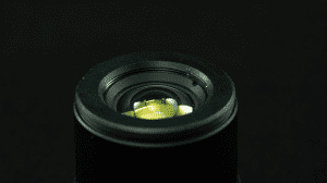
Structure of Lens
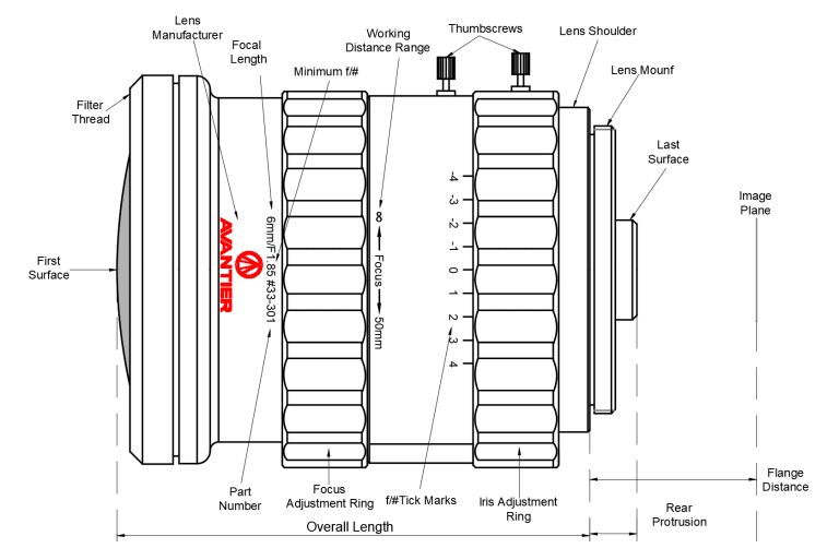
- Focus Adjustment Ring: Changes the focal distance (working distance) between the lens and the object.
- Iris/Aperture Ring: Adjusts the F-number (f/#) to control light intake and image quality.
- Thumbscrews: Lock settings in place to prevent accidental shifts.
- Lens Information: Printed on the barrel—includes focal length, minimum f/#, and model number.
- Working Distance Range: Indicates the focusing range of the lens.
- f/# Tick Marks: Help set the aperture precisely.
- Filter Thread: Mounting point for filters; adapters may be needed for wide-angle lenses.
- Camera Mount: Connects the lens to a camera (e.g., C-Mount, F-Mount, TFL-Mount).
- Rear Protrusion: Portion that extends into the camera—must avoid sensor or filter interference.
- First and Last Optical Surfaces: Define working distance and optical path.
- Lens Shoulder & Flange Distance: Ensure proper mounting alignment and sensor positioning.
- Image Plane: Where the lens focuses light—typically the camera sensor.
Cooled vs. Uncooled Infrared Detectors
Cooled IR Detectors
- Used in: MWIR and LWIR imaging
- Cooling Required: Yes (often liquid nitrogen)
- Advantages:
- High sensitivity and image resolution
- Long detection range
- Applications: Aerospace, defense, high-end scientific imaging
Uncooled IR Detectors
- Used in: Mostly LWIR imaging
- Cooling Required: No
- Advantages:
- Compact, cost-effective
- Operates at room temperature
- Disadvantages: Lower sensitivity and slower response
- Applications: Civilian use, building inspection, automotive systems
Types of Infrared Lenses (IR Lenses)
Short-Wave Infrared (SWIR) Lenses
- Wavelength: 800–1700 nm
- Key Features:
- Works with reflected IR light
- High-resolution imaging
- Performs well in low-visibility environments (e.g., smoke)
- Applications:
- Semiconductor inspection
- Anti-counterfeiting
- Medical diagnostics
- Quality control and machine vision
Medium-Wave Infrared (MWIR) Lenses
- Wavelength: 3000–5000 nm (3–5 μm)
- Key Features:
- Captures emitted thermal radiation from hot objects
- Requires cooled detectors
- Higher resolution than LWIR
- Applications:
- Fire detection
- Engine diagnostics
- Military target acquisition
- Long-distance surveillance
How to Select the Right Infrared Lens
Matching Wavelength Bands to Application Needs
The first and most critical step is to align the IR lens’s wavelength band with your application’s requirements. Each band offers distinct advantages:
- Short-Wave Infrared (SWIR, 0.9-1.7μm): Ideal when reflected light imaging is paramount. SWIR lenses excel in applications requiring strong penetration through smoke/fog, high contrast, and the ability to capture microstructures. Think semiconductor wafer defect detection, covert night vision, and biometric identification.
- Mid-Wave Infrared (MWIR, 3-5μm): Best suited for high-temperature object thermal radiation detection. MWIR lenses offer high atmospheric transmittance and often provide superior sensitivity compared to long-wave IR. They are perfect for industrial equipment overheating warnings (e.g., kilns) and long-range target identification in border surveillance.
- Long-Wave Infrared (LWIR, 8-14μm): The go-to for perceiving thermal radiation from objects at room temperature without needing an active light source. LWIR lenses are highly resistant to environmental interference. Common uses include human body temperature measurement (e.g., medical screening), power equipment heat leakage detection, and general night security surveillance.
Core Technical Parameters for Optimal Performance
Once the wavelength band is determined, delve into these technical specifications to fine-tune your lens selection:
- Focal Length and Field of View (FOV):
- For large-area monitoring (e.g., ports, forest fire prevention), opt for wide-angle lenses (e.g., 45° FOV).
- For long-distance recognition and detailed inspection of remote targets, telephoto lenses (e.g., 75mm focal length) are essential.
- For dynamic scenes like UAV inspections, zoom lenses offer flexibility, allowing you to balance resolution with an appropriate F-number (typically 0.7-1.2).
- Infrared Resolution and Thermal Sensitivity:
- Resolution: While 640 x 480 pixels (LWIR) often suffices for most scenarios, 1280 x 1024 pixels (SWIR) is crucial for precision detection in applications like semiconductor inspection.
- Net Equivalent Temperature Difference (NETD): A lower NETD indicates higher thermal sensitivity. An NETD of ≤ 40mK (LWIR) allows for the identification of a 0.05°C temperature difference, whereas below 30mK is necessary for sensitive tasks such as medical temperature measurement.
- Optical Materials and Coating Technology:
- SWIR lenses often incorporate chalcogenide glass or are designed to pair efficiently with InGaAs sensors, aiming for a photon detection efficiency above 70%.
- LWIR lenses are typically crafted from high-purity germanium glass and require anti-reflection coatings to minimize energy loss and maximize light transmission.
Adapting to Special Environmental Demands
The operational environment significantly impacts lens choice. Consider these factors for specialized applications:
- Extreme Temperatures:
- For industrial scenes involving high temperatures, select high-temperature resistant lenses (e.g., those supporting up to 2000°C).
- Outdoor equipment necessitates robust protection, such as IP68-rated enclosures constructed from 316 stainless steel to guard against corrosive elements like salt fog.
- Light Conditions:
- In no-light environments at night, LWIR non-cooling lenses with a large aperture (F1.0 or lower) are preferable to maximize light intake.
- For active lighting scenes, ensure your SWIR lens matches the laser wavelength (e.g., 1.55μm) and that its field of view is consistent with the laser to avoid wasted light.
- Infrared Illuminator Matching:
- For applications like gate monitoring, the infrared light beam angle should be slightly narrower than the lens field angle. This helps prevent the “edge light screen effect,” where uneven light distribution causes bright spots at the image edges, obscuring the central view.
- In complex lighting scenarios, a complementary strategy using both wide and narrow-angle lights can optimize thermal imaging uniformity.
Simple IR lens Selection WorkFlow
| Step | Key Considerations | Typical Parameter Examples |
|---|---|---|
| 1. Fixed Band | Detect target temperature/reflection characteristics | 20-2000℃ selects MWIR/LWIR |
| 2. Select Focal Length | Detection range and coverage | Wide Angle 45° vs. super telephoto 75mm |
| 3. Core Performance | Resolution, NETD, transmittance | 640 x 480 pixels + 30mK sensitivity |
| 4. Test Compatibility | Interface sealing, detector matching | Fascia connection dustproof is better than thread |
Applications of Infrared Lenses
Medical Instrumentation
Infrared lenses are widely used in thermal imaging and non-invasive diagnostics. Equipped with MWIR or LWIR lenses, infrared thermal cameras can detect subtle surface temperature variations on the skin—useful in identifying:- Inflammation
- Circulatory issues
- Cancerous growths
- Endoscopic systems
Life Sciences
In life sciences and pharmaceutical research, infrared lenses enable precise NIR light focusing for:- Near-infrared (NIR) spectroscopy
- Chemical composition analysis
- Food quality inspection
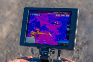
Surveillance & Security
Infrared lenses play a pivotal role in night vision and thermal imaging surveillance.- SWIR lenses enhance visibility in low-light or obscured environments (smoke, fog, darkness).
- LWIR lenses are widely used in thermal cameras to detect intruders and monitor infrastructure in all weather conditions.
- Border security
- Critical infrastructure monitoring
- Law enforcement and crowd control
Aerospace & Defense
Defense systems rely heavily on MWIR and LWIR lenses for:- Long-range surveillance
- Target acquisition and tracking
- Navigation in low-visibility conditions
- SWIR imaging also supports target recognition and identification, especially in harsh or camouflaged environments.


Industry Use Cases at a Glance
Application Area | Typical Infrared Lens Types | Use Cases |
Life Sciences | NIR, SWIR | Spectroscopy, chemical imaging |
Security & Surveillance | SWIR, LWIR | Night vision, perimeter monitoring |
Medical | MWIR, LWIR | Thermography, diagnostics, endoscopy |
Aerospace & Defense | MWIR, LWIR, SWIR | Reconnaissance, threat detection |
Future Trends and Technologies
Enhanced Performance
Advances in optical materials and coatings will lead to:- Higher IR transmission efficiency
- Lower aberrations and distortion
- Improved resolution and clarity
Miniaturization
With increasing demand for compact devices, IR lenses are being designed for:- Wearable medical monitors
- Lightweight UAV and drone systems
- Portable inspection tools
Multi-Spectral Imaging
Next-gen IR lenses may combine multiple wavelength bands (e.g., SWIR + MWIR), enabling:- Simultaneous data capture across the IR spectrum
- Advanced imaging for agriculture, environment, and security
AI & Machine Learning Integration
When paired with AI-powered imaging systems, IR lenses can support:- Real-time threat recognition
- Automated quality control
- Predictive maintenance in industrial settings
Emerging Applications
As infrared imaging becomes more accessible, new use cases are emerging in:- Smart agriculture
- Energy efficiency and HVAC diagnostics
- Waste sorting and recycling
In Summary
Infrared lenses are advancing rapidly—enabling smarter, faster, and more accurate imaging across critical sectors. Whether it’s improving patient care, enhancing national security, or enabling better environmental analysis, IR lenses will remain at the forefront of innovation.
Related Content


WE CAN HELP YOU!
Contact us NOW for sales & expert advice.