

Surface Figure Control for High-Performance Aspheric Mirrors in Space Optics
High-performance aspheric mirrors used in space optical systems require more than a low final RMS value. Surface figure, roughness, subsurface condition, edge behaviour, spatial-frequency error, and metrology uncertainty must all be controlled within the same manufacturing strategy.
This application note examines a representative space mirror assembly consisting of an approximately 250 mm spherical primary mirror and an aspheric secondary mirror. The completed optics achieved surface figure accuracy better than λ/20, with visible broadband reflectivity above 90% after coating.
For an overview of aspheric mirror configurations, optical advantages, and application areas, see Avantier’s Aspheric Mirrors resource.
Reference Performance
| Parameter | Reference value |
| Primary mirror aperture | ~250 mm |
| Primary mirror radius of curvature | ~700 mm |
| Secondary mirror | Aspheric |
| Final surface figure | Better than λ/20 |
| MRF surface figure improvement | ~λ/8 to λ/25 RMS |
| Surface roughness after MRF | <0.5 nm Ra |
| IBF surface figure improvement | ~λ/24 to λ/30 RMS |
| Visible broadband reflectivity after coating | >90% |
The manufacturing objective was not simply to reach the final surface figure specification. The process had to prevent upstream material damage, control errors across different spatial-frequency bands, and maintain sufficient measurement accuracy for each corrective iteration.
1. Principal Error Sources
For a high-performance aspheric mirror, several error mechanisms can influence the final optical surface simultaneously.
| Error source | Potential effect | Primary control method |
| Grinding-induced subsurface damage | Microcracks, residual stress, reduced structural strength | Controlled damage-layer removal |
| Low-frequency figure error | PV/RMS non-conformance | Progressive polishing and MRF |
| MRF edge effects | Edge roll-off or local figure degradation | Edge allowance and scan-path optimisation |
| Mid-spatial-frequency error | Reduced contrast, MTF degradation, increased stray light | PSD analysis and process selection |
| Residual local surface error | Local protrusions and periodic structures | IBF correction |
| Metrology-system error | Incorrect correction map and false convergence | Compensated interferometry and calibration |
| Process-to-process variation | Accumulated figure error | Closed-loop inspection and correction |
The appropriate fabrication route depends on more than optic diameter or material alone. Aspheric departure, local slope, clear aperture, surface figure, roughness, substrate properties, and the available verification method all affect process selection. These factors are discussed more broadly in Aspheric Manufacturing: Precision Fabrication and Metrology for Lenses and Mirrors.
2. Substrate Preparation and Subsurface Damage Control
2.1 Starting Material
Low-expansion glass-ceramic materials such as Zerodur are well suited to precision space mirrors because of their very low coefficient of thermal expansion. In the reference process, the material had a CTE of approximately:
0 ± 0.02 × 10⁻⁶/K
Low thermal expansion helps preserve surface figure as temperature changes, but thermal stability alone does not guarantee a suitable precision-optical substrate.
Milling and grinding can leave a damaged subsurface layer containing microcracks and residual stress. In the reference case, the affected layer was approximately:
30–50 μm deep.
If this layer remains before polishing, subsequent material removal can expose defects or release residual stress, reducing the predictability of figure convergence.
2.2 Controlled Damage-Layer Removal
Chemical etching was used to remove the damaged layer before precision polishing. The process window required sufficient removal to eliminate grinding damage without unnecessarily altering curvature or dimensional accuracy.
Typical targeted removal was: 50–80 μm
For the reference component, process development evaluated acid composition, temperature, immersion time, and agitation method. A controlled etching process at approximately 60°C for about 15 minutes removed approximately: 60 μm of surface material.
The measured three-point bending strength increased from approximately:
35 MPa before etching → more than 58 MPa after etching
while the surface-profile PV variation before and after treatment was maintained within approximately: ±0.1 μm.
The important manufacturing consideration is that damage-layer removal must itself remain a controlled optical process. Removing subsurface damage at the expense of figure or dimensional stability simply transfers the error to the next manufacturing stage.
3. Progressive Surface-Figure Convergence
Surface correction was divided into stages so that each manufacturing process operated within an appropriate error range.
| Manufacturing stage | Primary function | Reference result |
| Milling / grinding | Near-net form generation and bulk material removal | PV within ~5 μm |
| Initial polishing | Roughness reduction and low-frequency correction | ~λ/5 to λ/10 RMS |
| Magnetorheological finishing (MRF) | Deterministic figure correction | ~λ/8 to λ/25 RMS |
| Ion beam figuring (IBF) | Residual local and higher-frequency correction | ~λ/24 to λ/30 RMS |
During milling and grinding, diamond tooling was used for relatively high-rate material removal until the surface approached the required geometry. Initial polishing then reduced roughness and larger low-frequency errors before deterministic correction began.
This staged approach prevents low-removal-rate processes from being used inefficiently for large-amplitude correction.
For a broader overview of Avantier’s grinding, polishing, MRF, and related optical production capabilities, see Lens Manufacturing Process. For the factors used to select between fabrication routes for different aspheric geometries, see Aspheric Manufacturing: Precision Fabrication and Metrology for Lenses and Mirrors.
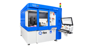
4. Magnetorheological Finishing: Deterministic Figure Correction
MRF was used after the surface had entered a suitable error range for deterministic correction.
The process uses a characterised removal function and calculated dwell-time distribution to selectively remove material from the measured high regions of the optical surface. Its manufacturing value therefore depends on two factors:
- stability of the removal function; and
- accuracy of the measured error map used to calculate dwell time.
For the aspheric secondary mirror in the reference assembly, MRF reduced the surface figure error from approximately: λ/8 RMS → λ/25 RMS
while the resulting surface roughness was reduced to: Ra <0.5 nm.
Edge Control
MRF is sensitive to conditions near the edge of the optic because the removal footprint cannot interact with the surface in the same way as it does within the full working aperture.
Without suitable process compensation, this can cause edge roll-off or local figure degradation.
The reference process used reserved edge regions and optimised scan paths to limit the region affected by edge effects to approximately: 2 mm from the edge.
This is particularly relevant when the specified clear aperture approaches the physical diameter of the optic. Clear-aperture requirements and usable edge allowance should therefore be considered when defining both the optical specification and manufacturing route.
More information on Avantier’s precision polishing and MRF capabilities is available in the Lens Manufacturing Process overview.
5. Ion Beam Figuring for Residual Error Correction
After the dominant figure error has been reduced, residual local and higher-spatial-frequency errors may require a smaller and more localised correction mechanism. Ion beam figuring removes material by physical sputtering with a focused ion beam inside a vacuum environment. Because the process is non-contact, it introduces no direct mechanical polishing load onto the optic.IBF is particularly useful when:
- the remaining figure error is relatively small;
- localised correction is required;
- the optic is already highly polished;
- mechanical contact should be minimised; or
- residual mid- or higher-frequency structures remain after preceding processes.
6. PSD-Based Control of Mid-Spatial-Frequency Error
PV and RMS are necessary surface-quality metrics, but they do not fully describe the spatial distribution of surface error.
Two optical surfaces with similar RMS values may have substantially different spatial-frequency content. Periodic or mid-spatial-frequency structures can affect system performance even when the overall RMS requirement is satisfied.
For the reference process, particular attention was given to surface errors with spatial wavelengths of approximately: 0.1–10 mm.
These mid-spatial-frequency errors can influence:
- point spread function (PSF);
- modulation transfer function (MTF);
- image contrast; and
- stray-light performance.
Power spectral density (PSD) analysis was therefore used to evaluate the surface across spatial-frequency bands rather than relying solely on aggregate PV and RMS values.
The manufacturing processes could then be applied according to the dominant error spectrum:
| Error regime | Primary control approach |
| Low-frequency / overall figure | Conventional polishing and MRF |
| Residual mid-spatial-frequency structure | MRF process optimisation and IBF |
| Higher-frequency residuals / microtopography | Final correction and roughness control |
The combined use of MRF, IBF, and PSD analysis provided a method for controlling not only the magnitude of surface error but also its spatial distribution.
For aspheric optics, this distinction should ideally be addressed during specification review. A demanding RMS value without corresponding spatial-frequency requirements may not fully define the surface behaviour that matters to the optical system.
7. Metrology for Deterministic Correction
Deterministic figuring requires a sufficiently accurate error map. As surface tolerances move into the tens-of-nanometres regime, metrology error can become comparable to the manufacturing error being corrected.
Aspheric interferometric measurement therefore requires a reference wavefront that matches the nominal aspheric surface.
In the reference assembly, the aspheric secondary mirror was measured using a three-lens refractive compensator. The compensator design targeted a residual wavefront error below: λ/100
with angular alignment controlled to less than: 5 arcsec.
A computer-generated hologram (CGH) calibration path was also incorporated to evaluate systematic errors within the measurement configuration.
The CGH achieved diffraction efficiency above: 30%
and calibration indicated a compensator wavefront error of approximately: λ/85.
For more complex aspheric surfaces, the source process notes indicate CGH-based measurement accuracy in the approximate range of: λ/70 to λ/100
provided that positional, tilt, and off-axis alignment errors are adequately controlled.
The broader principles behind selecting fabrication and aspheric metrology strategies are covered in Aspheric Manufacturing: Precision Fabrication and Metrology for Lenses and Mirrors.
8. Closed-Loop Manufacturing and Inspection
Final inspection alone is insufficient for a deterministic surface-correction process.
Inspection points were therefore established between major manufacturing stages. The measured surface condition was used to determine whether the optic was ready to move to the next process and, during final figuring, to calculate the next corrective iteration.
The control loop can be represented as:
Interferometric measurement
→ surface-error map
→ error separation and analysis
→ dwell-time calculation
→ corrective figuring
→ remeasurement
→ acceptance or next iteration
During precision figuring, inspection results were fed back to the manufacturing equipment so that dwell-time parameters could be updated for each iteration.
This approach is particularly important because apparent convergence in RMS does not necessarily indicate that all relevant error components are improving. Figure, edge behaviour, PSD, roughness, and measurement uncertainty should be reviewed together before the next correction is calculated.
9. Reference Process Results
The principal results of the reference manufacturing route are summarised below.
| Parameter | Reference result |
| Low-expansion glass-ceramic CTE | ~0 ± 0.02 × 10⁻⁶/K |
| Grinding-induced damage depth | ~30–50 μm |
| Typical controlled etch range | ~50–80 μm |
| Reference material removal by etching | ~60 μm |
| Three-point bending strength | ~35 MPa → >58 MPa |
| Surface-profile variation during etching | within ±0.1 μm PV |
| Post-grinding surface figure | PV within ~5 μm |
| Initial polished surface figure | ~λ/5–λ/10 RMS |
| MRF correction | ~λ/8 → λ/25 RMS |
| Roughness after MRF | <0.5 nm Ra |
| Controlled MRF edge-effect region | ~2 mm |
| IBF correction | ~λ/24 → λ/30 RMS |
| Compensator design residual WFE | <λ/100 |
| Measured compensator WFE after CGH calibration | ~λ/85 |
| Final mirror surface figure | Better than λ/20 |
| Visible broadband reflectivity after coating | >90% |
These values should be understood as results from the reference manufacturing case rather than universal specifications. The appropriate process window depends on the substrate, geometry, aspheric departure, local slope, aperture, surface requirements, and verification strategy.
10. Engineering Checklist for High-Performance Aspheric Mirrors
Before releasing a demanding aspheric mirror for manufacture, the following parameters should be defined or reviewed together:
- Optical material: thermal expansion, stiffness, homogeneity, and process compatibility
- Physical aperture and clear aperture: including available edge allowance
- Aspheric prescription: including departure from the best-fit sphere and local slope
- Surface figure: PV and/or RMS requirement and measurement wavelength
- Surface roughness: including the required spatial bandwidth
- Mid-spatial-frequency requirements: PSD or equivalent limits where system performance requires them
- Subsurface damage requirements: particularly after aggressive generation or grinding
- Coating specification: spectral range, reflectivity, and environmental requirements
- Metrology strategy: including compensator, CGH, stitching, or other required methods
- Measurement uncertainty: relative to the manufacturing tolerance being verified
- Support and environmental conditions: where they can affect measured figure
- Inspection points: defining when the process should transition from bulk correction to deterministic finishing
For a broader explanation of how these parameters influence fabrication-route selection for lenses and mirrors, refer to Aspheric Manufacturing: Precision Fabrication and Metrology for Lenses and Mirrors.
For component-level information and typical application areas, see Custom Aspheric Mirrors.
Discuss an Aspheric Mirror Specification
When the surface figure reaches the λ/20 range and beyond, manufacturability cannot be evaluated from the RMS specification alone. Substrate condition, aspheric geometry, spatial-frequency requirements, clear aperture, finishing process, and metrology strategy must be considered together.
Avantier supports custom high-performance optical components from specification review through precision fabrication, polishing, metrology, and coating.
If you are developing an aspheric mirror with demanding surface figure, roughness, PSD, or verification requirements, contact Avantier’s optical engineering team to review the specification, manufacturing route, and metrology strategy before production.
Relevant Technical Resources
Custom Aspheric Mirrors
Design considerations, applications, material options, and custom aspheric mirror capabilities.
Lens Manufacturing Process
An overview of optical generation, polishing, MRF, metrology, coating, and related manufacturing processes.
Aspheric Manufacturing: Precision Fabrication and Metrology for Lenses and Mirrors
How aspheric departure, local slope, clear aperture, material, surface specification, and verification requirements influence fabrication and metrology route selection.





WE CAN HELP YOU!
Contact us NOW for sales & expert advice.