

Design Trade-offs in Compact Multispectral Reflective Imaging Systems
Advanced imaging systems for aerospace and environmental remote sensing are increasingly expected to combine multiple spectral bands, compact packaging, high image quality, and stable operation in demanding environments.
For systems spanning visible, near-infrared, and thermal infrared wavelengths, the challenge is not simply achieving good optical performance in each channel independently. The harder engineering problem is balancing cross-band performance, detector sampling, packaging constraints, obscuration, alignment sensitivity, and manufacturability within one architecture.
A reflective multichannel optical system can provide a strong foundation for this type of design, particularly when a compact folded optical path is required. But the value of the architecture depends on how those trade-offs are managed at the system level.
Depending on the system architecture, spectral separation may be introduced downstream using wavelength-selective elements or dedicated channel paths. These elements introduce additional considerations such as coating bandwidth, transmission efficiency, and registration stability.
Starting with the Architecture: Why a Shared Reflective Path Matters
A reflective architecture is attractive for multispectral systems because it avoids the wavelength-dependent refractive behavior associated with transmissive optical elements and can support a broad spectral range with fewer chromatic effects. It also makes it possible to share portions of the optical path across multiple channels. In practice, however, a shared optical path introduces its own constraints. Visible, near-infrared, and thermal infrared channels do not have identical imaging requirements. Their detectors may differ in pixel pitch, active area, sampling frequency, and preferred F-number. Diffraction also scales with wavelength, so an optical configuration that is comfortably diffraction-limited in the thermal infrared may still require tighter control of aberrations in the visible channel. The design therefore becomes a multi-objective optimization problem rather than a simple exercise in chromatic correction. Typical competing variables include:- Effective focal length
- Entrance aperture
- F-number
- Field of view
- Central obscuration
- Detector format and pixel pitch
- Optical MTF
- Wavefront error
- Mechanical envelope
- Alignment sensitivity
- Manufacturing tolerances
Packaging versus Optical Performance
A Cassegrain configuration is particularly useful when long effective focal length must be achieved within a short mechanical envelope. The folded optical path allows a compact structure while retaining the benefits of a relatively long focal length. This packaging efficiency comes with trade-offs. Increasing central obscuration redistributes energy in the diffraction pattern and changes the MTF response, often reducing contrast over parts of the spatial-frequency range. It also reduces effective collecting area. Reducing the secondary mirror size can reduce obscuration and increase effective collecting area, but may increase vignetting or constrain field of view. Similarly, shortening the physical length of the system may require more aggressive mirror curvatures or tighter mirror spacing, which can increase aberration sensitivity and tighten manufacturing or alignment tolerances. A practical design therefore needs to identify an acceptable operating region rather than a single idealized optimum. Representative system-level constraints might be expressed as:- Effective focal length: 250–350 mm
- Entrance aperture: 100 mm
- F-number: F/2.8
- Full field of view: 4°
- Maximum central obscuration ratio:25%
Cross-Band Optimization Is Not a Single-Wavelength Problem
One of the most important design challenges in a multispectral reflective system is maintaining useful performance across wavelength bands with very different physical behavior. At shorter wavelengths, small residual aberrations can produce a significant reduction in image quality because the diffraction spot is relatively small. At longer wavelengths, diffraction becomes more dominant, which may relax some aberration requirements but can make aperture size and F-number more important. This means that the same wavefront error does not necessarily have the same practical impact in each channel. The original design approach addresses this by optimizing aberrations on a per-channel basis while maintaining a shared system architecture. For engineering purposes, it is useful to think of cross-band optimization in three layers:- Shared geometry Mirror curvature, spacing, aperture, and optical path must remain compatible with all spectral channels.
- Channel-specific imaging performance Each channel must meet its own MTF, wavefront, and detector-sampling requirements.
- System-level balance Improving one channel should not push another below its acceptable performance threshold.
- Visible-band MTF at 50 lp/mm
- NIR MTF at 40 lp/mm
- Thermal IR wavefront error: 0.1λ RMS at 10 μm
- RMS spot radius across multiple field points
- Distortion
- Vignetting
- Obscuration
- Telecentricity, where required
- Sensitivity to alignment errors
Sampling Must Be Designed Together with the Optics
Optical MTF alone does not determine image quality. The detector introduces its own spatial sampling characteristics, and the relationship between optical resolution and detector sampling is critical. For each channel, the detector pixel pitch defines a Nyquist spatial frequency: For a detector with pixel pitch pp, the Nyquist frequency is: fNyquist = 1 / (2p) When pixel pitch is expressed in micrometers: fNyquist [lp/mm] = 500 / p [μm] A useful engineering target may be: Optical MTF ≥ 0.4 at detector Nyquist However, this requirement should not be applied blindly. If the optics significantly outperform the detector sampling, some optical performance may be unused. If the optical cutoff frequency falls well below Nyquist, the detector may be oversampling an already blurred image. If the system is heavily undersampled, aliasing may become a more important limitation than optical blur. The best design balances:- Optical MTF
- Detector MTF
- Pixel pitch
- Nyquist frequency
- Expected signal-to-noise ratio
- Image processing requirements
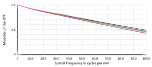
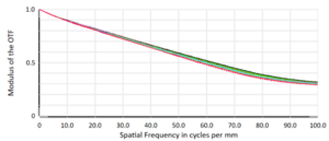
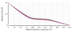
The different MTF roll-off characteristics across the visible, near-infrared, and long-wave infrared channels also illustrate why a common spatial-frequency criterion is not necessarily meaningful across all bands. Each channel should be evaluated relative to its wavelength range, detector sampling, and intended spatial-resolution requirement.
System MTF Matters More Than Optical MTF Alone
The MTF of the optical system is only one contributor to overall image quality.
A more complete system-level analysis considers the combined effect of:
- Optical MTF
- Detector aperture MTF
- Sampling
- Motion blur
- Platform jitter
- Focus error
- Manufacturing error
- Image processing
Before detector sampling is considered, the system transfer function can be approximated as the product of the major blur contributions:
MTFpre-sampling ≈ MTFoptics × MTFdetector × MTFmotion × MTFother
Detector sampling should then be evaluated separately, particularly with respect to Nyquist frequency and aliasing risk. This distinction is important in airborne and spaceborne systems, where platform motion, structural vibration, detector aperture effects, and sampling can all consume part of the available image-quality budget.
For a practical engineering program, it is therefore more useful to define performance at the system level—for example:
Pre-sampling MTF ≥ 0.25 at 50: detector Nyquist or mission spatial frequency
together with an explicit sampling criterion based on pixel pitch, Nyquist frequency, and allowable aliasing.
This avoids treating optical MTF as the only image-quality metric and provides a more realistic basis for balancing optics, detector selection, and platform-level performance.
Wavefront Error Should Be Interpreted by Wavelength
Wavefront error is another useful metric, but its interpretation must remain wavelength-dependent. The same absolute surface or alignment error represents a larger fraction of a wavelength in the visible than in the thermal infrared. For a given resulting optical-path difference, the corresponding wavefront error represents a larger fraction of a wavelength in the visible than in the thermal infrared. As a result, mechanical or alignment errors that are acceptable for a long-wave channel may still be performance-limiting for a visible channel. A multispectral tolerance budget should therefore avoid treating a single wavefront criterion as universally representative. Instead, channel-specific targets may be used, for example:- Visible channel: 0.08λ RMS
- NIR channel: 0.07λ RMS
- Thermal IR channel: 0.1λ RMS at 10 μm
Tolerance Analysis Should Identify What Actually Drives Performance
A nominally optimized optical design is only useful if it can be manufactured and aligned. The more important question is not simply whether tolerances are “tight,” but which tolerances dominate performance degradation. In a Cassegrain architecture, common sensitivities may include:- Secondary mirror decenter
- Secondary mirror tilt
- Primary-to-secondary spacing
- Detector axial position
- Detector tilt
- Mirror figure error
- Mounting-induced deformation
- A highly sensitive secondary-mirror tilt may justify an active or precision alignment mechanism.
- A less sensitive axial spacing may be handled with standard machining tolerances.
- Detector focus sensitivity may justify shim adjustment during final integration.
- Mirror figure error may need to be allocated separately between low-order and mid-spatial-frequency components.
- Mirror decenter: ±25 μm
- Mirror tilt: ±15 arcsec
- Axial spacing: ±50 μm
- Detector focus position: ±30 μm
- Surface figure: 0.02 waves RMS
Tolerance Allocation Should Be Linked to the Image-Quality Budget
Tolerance analysis becomes most useful when it is tied directly to a performance budget. Instead of asking whether the as-built system matches the nominal design exactly, the engineering question is whether expected manufacturing and integration errors still leave sufficient margin. A typical budget may reserve separate portions of allowable MTF degradation or wavefront error for:- Nominal optical residual
- Mirror fabrication
- Mechanical assembly
- Alignment
- Temperature variation
- Platform deformation
- Detector positioning
Environmental Stability Must Be Included in the Optical Budget
For aerospace and environmental-monitoring platforms, the optical system does not operate under fixed laboratory conditions. Temperature variation can change mirror spacing, detector position, structural alignment, and in some materials the optical surface itself. Mechanical vibration and platform motion can introduce additional line-of-sight or image-quality errors. As a result, the optical design should be evaluated together with structural and thermal behavior. Relevant parameters may include:- Operating temperature range: -20°C to 50°C
- Maximum allowable focus shift: ±80 μm
- Maximum line-of-sight drift: ±50 μrad
- Allowable thermally induced MTF degradation: 10%
Cross-Band Registration Can Be as Important as Resolution
For multispectral sensing, sharp images alone are not always sufficient. If visible, NIR, and thermal channels are used together for classification, fusion, change detection, or quantitative analysis, the images must also remain geometrically registered. Registration errors can result from:- Different detector locations
- Magnification differences
- Distortion differences
- Thermally induced optical-path changes
- Mechanical drift
- Channel-specific focal-plane alignment
The Engineering Objective Is Balanced Performance
A compact multispectral reflective system is not optimized by maximizing one optical metric. The real design objective is to find a balanced solution that satisfies multiple constraints simultaneously:- Adequate aperture and light collection
- Appropriate focal length and field of view
- Optical performance matched to detector sampling
- Acceptable central obscuration
- Stable performance across spectral bands
- Controlled cross-band registration
- Realistic manufacturing tolerances
- Practical alignment strategy
- Environmental stability
- Compact mechanical packaging
Need Support with Optical Design or Imaging Optimization?
Developing a high-performance imaging system requires careful trade-offs across optical architecture, detector selection, image quality, tolerancing, and system integration. If you are working on a new imaging platform or looking to improve the performance of an existing optical system, Avantier’s engineering team can support you with optical design, multispectral system development, imaging optimization, MTF and wavefront analysis, and tolerance evaluation.
Contact us to discuss your application requirements and explore the right optical approach for your system.



WE CAN HELP YOU!
Contact us NOW for sales & expert advice.